|
|

EUROPEAN
SOUTHERN OBSERVATORY
Organisation Européenne pour des Recherches Astronomiques dans l'Hémisphère
Austral
Europäische Organisation für astronomische Forschung in der südlichen
Hemisphäre
VLT PROGRAMME
VERY
LARGE TELESCOPE
VLT
Software
---
Template
Instrument Software
User and
Maintenance Manual
Doc. No.: VLT-MAN-ESO-17240-1973
Issue: 5
Date: 13/01/2005
Name Date Signature
Prepared: A.Longinotti 13/01/2005
Name Date Signature
Approved: K.Wirenstrand
Name Date Signature
Released: K.Wirenstrand
VLT PROGRAMME * TELEPHONE:
(089) 3 20 06-0 * FAX: (089) 3 20 06 514
CHANGE RECORD
|
ISSUE |
DATE |
SECTION/PAGE AFFECTED |
REASON/INITIATION DOCUMENTS/REMARKS |
|
1.0 |
All |
First issue, containing only ICS part |
|
|
2.0 |
|
All |
Second issue, containing the whole instrument, including OS |
|
3 |
|
4.7.2 5.3 11.10.4 |
MAR2002, Added ICS stand-alone GUI, SPR VLTSW20010501, VLTSW20010502. |
|
4 |
|
3.2 Appendix B |
APR2003 |
|
5 |
|
2.2.1 3.2.1 Chapter 7 Chapter 8 11.5 App. A App. B |
New installation modules for locations other than the final one Added chapter on test Software Contents of modules updated Contents of configuration files removed Removed xxinsCreateNewInstrument (VLTSW20040136) Removed xxinsChangeEnvs (VLTSW20040136) |
TABLE OF CONTENTS
TABLE
OF CONTENTS 3
1 INTRODUCTION 7
1.1 Purpose 7
1.2 Scope 7
1.3 Applicable Documents 7
1.4 Reference Documents 8
1.5 Abbreviations and Acronyms 9
1.6 Glossary 9
1.7 Stylistic Conventions 9
1.7.1 Data Flow and Processor Model Diagrams 9
1.8 Naming Conventions 10
1.9 Problem Reporting/Change Request 10
2 OVERVIEW 11
2.1 Hardware architecture 11
2.1.1 Devices 11
2.1.2 Computers 11
2.1.3 LANs 11
2.1.4 Special connections 11
2.2 Software Architecture 13
2.2.1 Software Modules 13
2.2.2 Environments 13
2.2.3 Standards 13
3 INSTALLATION GUIDE 15
3.1 Requirements 15
3.1.1 Hardware 15
3.1.2 Software 15
3.2 Installation procedure 15
3.2.1 Installation at other locations 16
4 OPERATOR’S GUIDE 17
4.1 System Start-up 17
4.1.1 Log-in 17
4.1.2 Telescope availability 17
4.1.3 Midas availability 18
4.1.4 Instrument Software Start-up 18
4.1.5 Begin of operations 19
4.1.6 End of operations 19
4.2 System Shut-down 19
4.3 User Station 20
4.4 Observations with Templates 21
4.5 Alarms 21
4.6 Data files location 21
4.7 Engineering 21
4.7.1 OS Engineering GUI 21
4.7.2 ICS Engineering GUI 21
5 PROGRAMMER'S GUIDE 23
5.1 Instrument Modes 23
5.2 Subsystems Identifiers 23
5.3 ICS Software Devices 23
5.3.1 ICS Special devices 24
5.3.2 ICS Assemblies 24
5.4 Exposures 25
5.4.1 Exposure types 25
5.4.2 Exposure Id 25
5.4.3 Exposure Status 25
5.4.4 Exposure Parallelism 25
5.4.5 Exposure Life Cycle 25
5.4.6 Exposure execution 26
5.5 Operational States 26
5.6 Commands 26
5.6.1 OS Special commands 26
5.6.2 ICS Special commands 26
5.6.3 DCS Special commands 26
5.7 Tcl libraries 26
5.8 Dictionaries 26
5.9 Alias files 27
5.10 Configuration files 27
5.11 Setup files and keywords 27
5.11.1 OCS keywords 27
5.11.2 INS keywords 27
5.11.3 DCS keywords 28
5.12 FITS files 28
5.13 Public on-line database attributes 28
5.14 Operational logs 28
5.15 Templates 28
5.15.1 Acquisition Templates 29
5.15.2 Calibration Templates 29
5.15.3 Observation Templates 29
6 CONFIGURATION 30
6.1 Change Instrument Configuration Parameters 30
7 TEST 32
8 MAINTENANCE 33
8.1 General 33
8.1.1 Module xxins 33
8.1.2 Module dicXXXX 33
8.2 OS 33
8.2.1 Module xxo 33
8.2.2 Module xxopan 34
8.2.3 Module xxotsf 34
8.2.4 Module xxoseq 35
8.3 ICS 36
8.3.1 Module xxi 36
8.3.2 Module xxipan 37
8.3.3 Module xxidev 37
8.4 DCS 37
8.4.1 Engineering 37
8.5 MS 38
8.5.1 Maintenance Templates 38
8.5.2 Module xxmcfg 38
8.5.3 Module xxmseq 38
8.5.4 Module xxmtsf 38
9 FAQ AND TROUBLESHOOTING 39
9.1 Problems at System Start-up 39
9.1.1 Log-in fails 39
9.1.2 Start-up of GUIs fails 39
9.1.3 Start-up of control processes fails 39
9.1.4 xxiControl starts with a wrong simulation
level 39
9.1.5 TCCD starts with a wrong simulation level
and fails to go STANDBY 39
9.1.6 xxoControl tries to access sub-systems
declared as not available 39
9.1.7 Going ONLINE fails 39
9.2 Problems when running exposures 40
9.2.1 Cannot send commands to TCS or access tif 40
9.2.2 Templates cannot access Midas 40
10 ERROR DEFINITIONS 41
11 REFERENCE 42
11.1 Programs 42
11.1.1 Command Definition Table for program
xxoControl 42
11.2 Scripts 43
11.2.1 xxinsStartup 43
11.2.2 xxinsStart 44
11.2.3 xxinsStop 46
11.3 Include Files 48
11.4 Tcl libraries 49
11.4.1 xxoseqICS 49
11.5 Configuration files 50
11.6 Setup files 51
11.6.1 Example of
Reference Setup file 51
11.6.2 Example of Instrument Setup File 51
11.7 Templates 52
11.7.1 IR Imaging acquisition template 52
11.7.2 IR Imaging observation template 53
11.7.3 IR Spectroscopy acquisition template 54
11.7.4 IR Spectroscopy observation template 55
11.7.5 Optical Imaging acquisition template 56
11.7.6 Optical Imaging observation template 57
11.7.7 Optical Imaging bias calibration template 58
11.7.8 Optical Imaging flat-field calibration
template 59
11.7.9 Optical Imaging detector linearity
calibration template 60
11.7.10 Optical Imaging focus calibration template 61
11.8 FITS files 62
11.8.1 Example of FITS header 62
11.9 Log files 63
11.9.1 Example of Operational Log (FITS format) 63
11.10 Panels 64
11.10.1 OS Control 64
11.10.2 OS Status 65
11.10.3 OS Engineering 66
11.10.4 ICS stand-alone 68
11.11 Error files 70
11.11.1 xxoErrors.h 70
11.11.2 xxo_ERRORS 71
Appendix A. Create a new Instrument 73
A.1 OS sub-classing and method overloading 73
A.2 Add special commands to OS 73
A.3 Add special handling of set-up keywords in OS 73
A.4 Implement a class library for templates 73
A.5 Implement an ICS special device on LCU 73
A.6 Implement an ICS special device on WS 73
A.7 ICS WS sub-classing and method overloading 74
A.8 ICS WS Assemblies 74
Appendix B. Installation using different environments 75
The software described in this manual is intended to be used in the ESO VLT project by ESO and authorized external contractors only.
While every precaution has been taken in the development of the software and in the preparation of this documentation, ESO assumes no responsibility for errors or omissions, or for damage resulting from the use of the software or of the information contained herein.
The Template Instrument (called XXXX) is a fictitious instrument, which incorporates the basic functionality of VLT instruments.
It is supposed to help Instrumentation Software developers, by providing them with examples of code and related files. It is also used internally at ESO to validate, through a complete instrument, the Instrumentation Common Software packages before a new VLT sw release is issued.
This document is the User Manual of the Template Instrument Control Software.
This package is fully based on VLT Instrumentation Common Software packages, such as icb (base ICS, see [RD 16] and [RD 26]), boss (base OS, see [RD 17]), tpl (library for templates, see [RD 24]).pkgin (installation tool, see [RD 18]), ctoo (configuration tool, see [RD 25]) and stoo (startup tool, see [RD 19]).
This document can also
be used as template for the User and Maintenance Manual of another instrument.
This document covers only the control part of the Template Instrument Software. It does not deal with other parts of the Data Flow, such as the pipeline.
It is aimed at operators of the instrument and software developers, who are responsible for its installation and maintenance.
This document is also
aimed at software developers, who need to develop Instrumentation Software for
VLT instruments or in general instrumentation according to VLT standards.
It is also meant for ESO engineers, responsible for the integration of new VLT Software releases, to validate the VLT Instrumentation Common Software packages.
The following documents, of the exact issue shown, form a part of this document to the extent specified herein. In the event of conflict between the documents referenced herein and the contents of this document, the contents of this document shall be considered as a superseding requirement.
|
Reference |
Document Number |
Issue |
Date |
Title |
|
GEN-SPE-ESO-19400-0794 |
3 |
In preparation |
DICB - Data Interface Control Document |
|
|
VLT-SPE-ESO-10000-0011 |
3 |
In preparation |
VLT Software Requirements Specification |
|
|
VLT-PRO-ESO-10000-0228 |
2 |
In preparation |
VLT Software Programming Standards |
|
|
VLT-SPE-ESO-10000-2723 |
0.9 |
|
VLT Requirements for Scientific Instruments |
|
|
VLT-MAN-ESO-17210-0667 |
1.2 |
|
Guidelines for VLT applications. |
|
|
VLT-SPE-ESO-17212-0001 |
5 |
|
INS Software Specification |
|
|
VLT-SPE-ESO-17240-0385 |
4 |
|
INS Common Software Specification |
|
|
VLT-ICD-ESO-17240-19400 |
2.6 |
|
ICD between VCS and Archive |
|
|
VLT-ICD-ESO-17240-19200 |
1.3 |
|
ICD between VCS and OH |
The following documents are referenced in this document.
|
Reference |
Document Number |
Issue |
Date |
Title |
|
VLT-MAN-ESO-17200-0888 |
1.0 |
|
VLT Common Software Overview |
|
|
VLT-MAN-ESO-17200-0642 |
4 |
|
VLT Common Software Installation Manual |
|
|
VLT-SPE-ESO-17100-3439 |
1 |
In preparation |
Paranal Network/Computers Design Description |
|
|
VLT-MAN-SBI-17210-0001 |
3.7 |
|
LCU Common Software User Manual |
|
|
VLT-MAN-ESO-17210-0600 |
1.7 |
|
Motor Control sw User Manual API/ACI |
|
|
VLT-MAN-ESO-17210-0669 |
1.6 |
|
Motor Engineering Interface User Manual |
|
|
VLT-MAN-ESO-17210-0619 |
2.4 |
|
Central Control Software User Manual |
|
|
VLT-MAN-ESO-17210-0707 |
1.6 |
|
On Line Database Loader User Manual |
|
|
VLT-MAN-ESO-17210-0771 |
1.8 |
|
EVH User Manual |
|
|
VLT-MAN-ESO-17210-0770 |
1.8 |
|
Extended CCS User Manual |
|
|
VLT-MAN-ESO-17210-0690 |
5 |
|
Panel Editor User Manual |
|
|
VLT-MAN-ESO-17240-0853 |
3 |
|
INS Common sw - oslx User Manual |
|
|
VLT-MAN-ESO-17240-0672 |
1.6 |
|
CCD Detectors Control Software User Manual |
|
|
VLT-MAN-ESO-13640-1388 |
3 |
|
FIERA Control Software User Manual |
|
|
VLT-MAN-ESO-14100-1878 |
1.4 |
|
IRACE-DCS User Manual |
|
|
VLT-MAN-ESO-17240-0934 |
5 |
|
Base ICS User Manual |
|
|
VLT-MAN-ESO-17240-2265 |
4 |
|
Base OS Stub User Manual |
|
|
VLT-MAN-ESO-17240-1913 |
4 |
|
Installation Tool for VLT Sw packages |
|
|
VLT-MAN-ESO-17240-2153 |
4 |
|
INS Startup Tool User Manual |
|
|
VLT-MAN-ESO-17220-0737 |
3 |
|
HOS - Sequencer User Manual |
|
|
P.Ward, S.Mellor, Yourdon Press, |
|
1985 |
Structured Development for Real-Time Systems |
|
|
J. Rumbaugh et. al., Prentice Hall, |
|
1991 |
Object-Oriented Modeling and Design |
|
|
VLT-MAN-ESO-17220-1999 |
4 |
|
Broker for Observation Blocks User Manual |
|
|
VLT-MAN-ESO-17240-2240 |
4 |
|
INS Common Software for Templates |
|
|
VLT-MAN-ESO-17240-2325 |
4 |
|
INS Configuration tool User Manual |
|
|
VLT-MAN-ESO-17240-2606 |
3 |
|
Base ICS GUI User Manual |
|
|
VLT-PLA-ESO-17240-2266 |
5 |
|
Acceptance Test Plan Template Document |
|
|
VLT-MAN-ESO_17200-0908 |
1.4 |
|
Tool for Automated Testing User Manual |
1.5 Abbreviations and Acronyms
This document employs several abbreviations and acronyms to refer concisely to an item, after it has been introduced. The following list is aimed to help the reader in recalling the extended meaning of each short expression:
|
CCS |
Central Control Software |
|
CPU |
Central Processing Unit |
|
DCS |
Detector Control Software |
|
ESO |
European Southern Observatory |
|
FITS |
Flexible Image Transport Format |
|
GUI |
Graphical User Interface |
|
HW |
Hardware |
|
ICS |
Instrument Control Software |
|
INS |
Instrumentation Software Package |
|
I/O |
Input/output |
|
ISAAC |
Infrared Spectrograph and Array Camera |
|
IWS |
Instrument Workstation |
|
LAN |
Local Area Network |
|
LCC |
LCU Common Software |
|
LCU |
Local Control Unit |
|
MS |
Maintenance Software |
|
N/A |
Not Applicable |
|
OMT |
Object Modeling Technique |
|
OO |
Object Oriented |
|
OOD |
Object Oriented Design |
|
OS |
Observation Software |
|
RAM |
Random Access Memory |
|
SW |
Software |
|
TAT |
Tool for Automated Testing |
|
TBC |
To Be Clarified |
|
TBD |
To Be Defined |
|
TCS |
Telescope Control Software |
|
TIM |
Time Interface Module |
|
TRS |
Time Reference System |
|
UIF |
(Portable) User Interface (Toolkit) |
|
UVES |
UltraViolet Visual Echelle Spectrograph |
|
VLT |
Very Large Telescope |
|
VME |
Versa Module Eurocard |
|
WS |
Workstation |
No special definition is introduced in this manual
The following styles are used:
bold
in the text, for commands, filenames, pre/suffixes as they have to be typed.
italic
in the text, for parts that have to be substituted with the real content before typing.
teletype
for examples.
<name>
in the examples, for parts that have to be substituted with the real content before typing.
bold and italic are also used to highlight words.
1.7.1 Data Flow and Processor Model Diagrams
Data Flow and processor Model Diagrams are based on De Marco/Yourdon notation for real-time systems [RD 21].
This implementation follows the naming conventions as outlined in [AD 03].
1.9 Problem Reporting/Change Request
The form described in [RD 02] shall be used.
This chapter gives a short overview of the instrument and its architecture.
The rest of the manual is organized as follows:
· Chapter 3 is the installation guide.
· Chapter 3.2.1 is the operator’s guide, which describes how to operate the instrument at various levels.
· Chapter 5 is the programmer’s guide, which describes in detail specific items, such as ICS devices and commands.
· Chapter 6 is the configuration guide, which describes in detail the configuration of the instrument.
· Chapter 7 contains the Maintenance Guide
· Chapter 9 contains a FAQ and troubleshooting tips specific to the instrument
· Chapter 10 contains the list of errors defined by the instrument application
· Chapter 11 contains the manual pages extracted from the source code.
· Appendix A describes how to create from scratch a new instrument starting from the Template Instrument code
The Instrument consists of:
· 24 devices, controlled by ICS, on 2 LCUs:
q 14 motorized
q 1 calibration lamp
q 1 shutter
q 7 sensors
q 1 special device
· 2 scientific detectors
q 1 infrared (IRACE controller)
q 1 optical (FIERA controller)
· 1 technical CCD camera (ACE controller)
The computers on which the Instrument Software runs are shown in Figure 1:
· Instrument Workstation (wxxxx) with ATM board
· ICS LCU 1 (lxxics1) with TIM board
· ICS LCU 2 (lxxics2) with TIM board
· TCCD LCU (lxxtccd) with TIM board
· IRACE UltraSparc (wxxirac) with ATM board
· FIERA UltraSparc (wxxfier) with ATM board
Note: the ATM board belongs to the standard configuration of Instrumentation Workstation and detectors UltraSparc. They are however not needed to run the Template Instrument Software and are mentioned here just to remind that for real instruments they should be present. The same consideration applies to the LCU TIM boards, whereby also in the case of real instruments the presence of the TIM board is mandatory only if the time precision needed on that LCU requires it.
The Instrument LAN follows the lay-out of VLT Control LANs (see [RD 03]) and is shown in Figure 1
The Template Instrument architecture does not foresee any special connection.
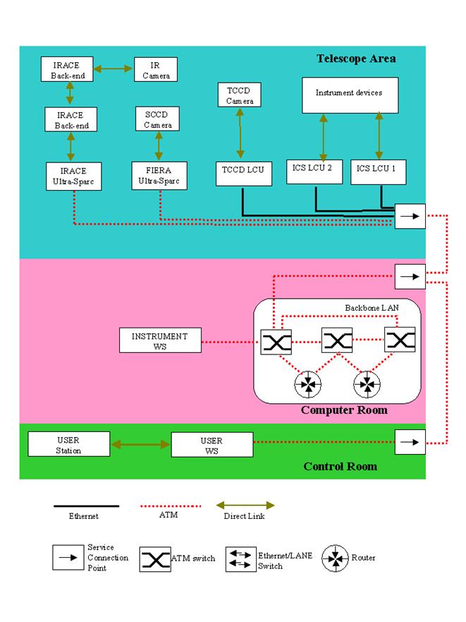
Figure 1 Hardware architecture
The architecture of the Control Software follows the VLT standard operational scheme and is shown in Figure 2
Observation Blocks, created with the P2PP toolkit, are sent to the Broker for Observation Blocks (BOB), which executes sequentially the templates defined in them.
In turn, each template consists normally of a sequence of commands sent to the OS Server. This process is responsible to interpret the commands received and convert them into commands for the controlled sub-systems (ICS, DCSs and TCS), taking care of the corresponding replies.
At the end of an exposure, the OS Server process is also responsible for merging all data/information into one FITS file and archive it, through the dedicated processes VOLAC/VCSOLAC/OLAS.
The XXXX Instrument Software consists of the following cmm modules (the prefix id xx corresponds to the Instrument ID):
|
Name |
INS
Module |
Platform |
Description |
|
xxins |
N/A |
WS |
Installation module for the final target configuration |
|
dicXXXX |
N/A |
WS |
FITS dictionaries |
|
xxi |
ICS |
WS |
ICS WS front-end and LCU simulator |
|
xxipan |
ICS |
WS |
ICS stand-alone GUI |
|
xxidev |
ICS |
LCU |
ICS special device |
|
xxo |
OS |
WS |
OS Server |
|
xxopan |
OS |
WS |
OS GUI |
|
xxoseq |
OS |
WS |
Observation Template scripts |
|
xxotsf |
OS |
WS |
Observation Template Signature Files |
|
xxmcfg |
MS |
WS |
Instrument Configuration Files |
|
xxmseq |
MS |
WS |
Maintenance Template scripts |
|
xxmtsf |
MS |
WS |
Maintenance Template Signature Files |
At locations other than Paranal, the following cmm modules are also used:
|
Name |
Location |
Platform |
Description |
|
xxmgar |
ESO Garching |
WS |
Installation and configuration module for targets DEV_ESO and CM_FULL |
|
xxmmpe |
MPE |
WS |
Installation and configuration module for targets DEV_MPE and INTEGRATION |
|
xxmoat |
OAT |
WS |
Installation and configuration module for targets DEV_OAT |
2.2.2 Environments
The Instrument uses the following CCS environments:
· wxxxx. IWS CCS environment (see RTAPENV)
· lxxics1. ICS LCU1 LCC environment.
· lxxics2. ICS LCU2 LCC environment.
· lxxtccd. TCCD DCS LCC environment.
· wxxfier. FIERA DCS CCS environment
· wxxtcs. TCS simulation CCS environment (see TCS_ENVNAME)
The Instrument Software is based on the standard packages distributed with VLT Software releases. In particular:
· TCCD DCS is based on the CCD Software (see [RD 13]).
· IR DCS is based on the IRACE Software (see [RD 15]).
· FIERA is based on the FIERA Software (see [RD 14]).
· ICS is based on the icb package (see [RD 16] and [RD 26]).
· OS is based on the BOSS package (see [RD 17])
· Templates are based on the tpl package (see [RD 24]).
· The Instrument Software installation is based on the pkgin package ([RD 18])
· The Instrument Configuration is based on the ctoo package (see [RD 25])
· The Instrument Software Start-up/Shutdown is based on the stoo package (see [RD 19]).

Figure 2 Template Instrument Architecture
The installation uses the VLT standard tool pkgin (see [RD 18]).
The following computers must be available (see section 2.1.2):
· One Instrument Workstation (HP, model supported by the VLT sw, see [RD 02]).
Furthermore, a more complete functionality is achieved if also the following computers (some or all of them) are available:
· Two LCUs for ICS
· One LCU for the TCCD
· One Sparc LCU for IRACE
· One Sparc LCU for FIERA
· The version of the UNIX Operating System installed on the IWS must be compatible with the VLT sw installation (see [RD 02])
· The VLT sw APR2005 or higher must be installed, according to [RD 02].
XXXX runs both on fullCCS or CCSLite.
The whole installation procedure must be executed as user xxxxmgr and will take at least 30 minutes. It consists of the following steps:
1.) Run the utility vccEnv and verify that the following CCS environments are known and correctly configured in the ACC database:
wxxxx for the instrument
lxxics1 for ICS LCU 1
lxxics2 for ICS LCU 2
lxxtccd for TCCD DCS LCU
wxxfier for the FIERA SLCU
2.) Verify that the environment variables INTROOT and INS_ROOT are defined.
% echo $INTROOT
% echo $INS_ROOT
3.) Verify that the file $HOME/.bobrc exists and is a symbolic link to $INTROOT/config/xxins.bobrc. If not, run:
% ln –s $INTROOT/config/xxins.bobrc $HOME/.bobrc
4.) Create an empty directory as root for the source code, e.g.:
% mkdir $HOME/XXXXSource
5.) Retrieve the installation module:
% cd $HOME/XXXXSource
% cmmCopy xxins [<version>]
Note: if the <version> parameter is omitted, the last version in the cmm archive is retrieved.
Note 2: In the case of the Template Instrument,
consortia should retrieve and use the version delivered with the last VLT
Software release, which has been
fully tested:
% cd <TAPE_ROOT_DIRECTORY>
% version=`grep "@(#)"
examples/insapp/XXXX/xxins/ChangeLog | awk '{print $4}'`
% cd $HOME/XXXXSource
% cmmCopy xxins $version
6.)
Start logMonitor,
to check possible errors during the installation:
% logMonitor &
7.) Build and install the Instrument Software
% pkginBuild xxins
During the installation the following directories are created:
INSTALL It contains logs and error logs of the installation.
ICS It contains all ICS modules (see 2.2.1)
OS It contains all OS modules (see 2.2.1)
MS It contains all MS modules (see 2.2.1), in particular xxmcfg, with the whole set of configuration files.
VLTSW_new It contains an upgraded version of modules, if any, belonging to VLT sw releases. If all modules as from VLTROOT are taken, this directory is missing.
8.) At the end of the installation, check for error logs in file $HOME/XXXXSource/INSTALL/pkginBuild.err.
3.2.1
Installation at other locations
Normally an
Instrument Software User Manual should describe only the installation procedure
needed in the operational configuration, i.e. at the Observatory, where all
computers used by that instrument are available. However, due to the nature of
the Template Instrument (example for all instrument developers, working at
different places under different hw configurations), we include also this
section, which describes the procedure to be followed at other locations, e.g.
a development site, where not necessarily the whole hw is available.
·
At development site MPE (example), whose configuration is:
o
All LCUs are available, but no hw is connected to
them
o
The FIERA Sparc is not available
o
The TCS simulation package is used
The installation module to be used is xxmmpe. The procedure therefore is:
% mkdir $HOME/XXXXSource
% cd $HOME/XXXXSource
% cmmCopy xxmmpe
% export TARGET=DEV_MPE
% pkginBuild xxmmpe
·
At the Integration site (here MPE, as example), whose configuration is:
o
All LCUs are available, but no hw is connected to
them
o
The FIERA Sparc is available
o
The TCS simulation package is used
The installation module to be used is xxmmpe. The procedure therefore is:
% mkdir $HOME/XXXXSource
% cd $HOME/XXXXSource
% cmmCopy xxmmpe
% export TARGET=INTEGRATION
% pkginBuild xxmmpe
·
At ESO Garching in the VLT Control Model, whose
configuration is:
o
All LCUs are available, but no hw is connected to
them
o
The FIERA Sparc is available
o
The VCM TCS is available
The installation module to be used is xxmgar. The procedure therefore is:
% mkdir $HOME/XXXXSource
% cd $HOME/XXXXSource
% cmmCopy xxmgar
% export TARGET=CM_FULL
% pkginBuild xxmgar
This chapter is intended to give instrument operators all information they need to work with the Instrument Software through its Graphical User Interface.
Note:
For Instruments operational at Paranal, after proper log-in on the User
Station, the CDE menu is customized to the specific Instrument to be operated,
such that dedicated options to start-up/shutdown control processes or
individual panels are provided. An example of such functionality is not
available for the Template Instrument yet.
In the following it is assumed that the installation (see chapter 3) has been successfully completed and environments are active.
In order to operate
the instrument properly, the user has to log-in
on all terminals in the User Station as user xxxx.
Unless otherwise specified, all UNIX shell commands, described in the next sections, have to be typed on a xterm window running on the Instrument Workstation.
After log-in, check that the environment variables needed to run properly the Instrument software are defined. To list the environment variables that should be defined type:
% osbEnvSet XXXX
The setting of these variables is done within the file $INTROOT/config/xxins-misc-all.env. This file is automatically sourced whenever you login or any new xterm is opened. Make sure that this is the case.
If TCS is supposed to be used, check with the telescope operator that it is running and ONLINE, before starting the Instrumentation Software.
In a development environment, where no real
telescope is available, the TCS simulation package is used. Run:
% xxinsStart –panel OS_ENGINEERING
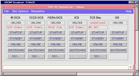
Figure 3 OS Engineering panel
The OS engineering panel (see Figure 3) pops-up.
·
If the
state of TCS Simulator is not ONLINE, press the button STARTUP: after a while
the state should change to ONLINE (if not, check, e.g. with scanei, that the
scan system between wxxxx and wxxtcs works properly).
·
Start the
TCS Sim. GUI
·
From the
TCS Simulation GUI, start the TCS Control and TCS User Panel
·
In the TCS
User Panel, press Preset Name zenith and wait till the dark gray background
color of the RA and DEC fields in the TCS Control Panel disappears.
·
Close TCS
Simulation GUI, TCS Control and TCS User Panel.
·
Simulate
TCS auto-guiding running, by selecting in the OS engineering panel the menu
item
Simulation à TCS à
Auto-guider à
Stop and then Start
·
Simulate
TCS active optics running, by selecting in the OS engineering panel the menu
item
Simulation à TCS à
Active Optics à
Stop and then Start
·
Close the
OS engineering panel (File à
quit).
Normally the Instrumentation Software does
not need any data reduction package installed and running on the Instrument
Workstation. The only exception is when such a package is needed to perform
on-line data reduction operations, whose results are then used by the
Instrumentation Software. Even in this case, normally no control process
accesses the on-line data reduction package, because this should be done at
templates level.
Some XXXX templates need a data reduction package and Midas is used for this purpose. Midas APR2005 must therefore be installed.
If this is not possible to run Midas, for
whatever reason, then templates can still be executed (e.g. for test purposes)
by setting the environment variable DEBUG_MIDAS (access to Midas from templates
is disabled):
%export DEBUG_MIDAS=1
4.1.4 Instrument Software Start-up
The system start-up is based on the common startup tool stoo (see [RD 19]).
After a new installation, or whenever some start-up configuration parameter needs to be changed, type on an xterm window:
% xxinsStartup
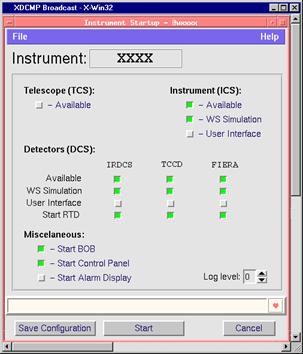
The Start-up GUI (Figure 4) pops-up. This panel allows defining which
sub-systems are available and at which level of simulation they should start,
in particular if they have to access the LCUs or they should simulate the LCU
functionality at WS level. It also allows specifying which GUIs will be
automatically started.
Figure 4 Startup panel
Finally, by pressing the button Start, all specified GUIs and sub-systems control processes are started. A log window shows the various phases of the startup procedure.
When successfully completed, the log window disappears and all sub-systems should be in state STANDBY.
If any error occurs, the log window remains active and shows the reason of the failure.
Once the start-up configuration is defined, the instrument can be started, or re-started, by directly typing on an xterm window:
%
xxinsStart
This command has the same effect of pressing the Start button in the start-up GUI.
Before being able to operate the instrument and take exposures, it has to be ONLINE.
On the OS Control panel (see Figure 5), check the global State. If it is not ONLINE, select the menu option
Instrument à ONLINE.
Please wait till the global State turns to ONLINE.
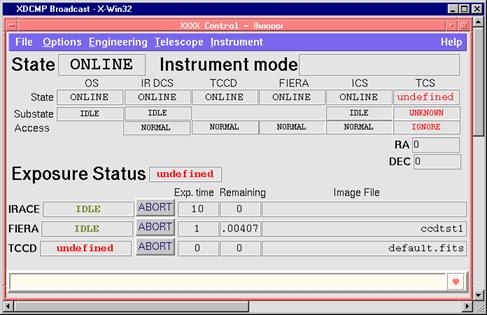
Figure 5 OS Control panel
After operating the instrument, whenever it is foreseen to leave it idle for long time (e.g. during daytime), the instrument has to be brought to a safe state, also called STANDBY.
On the OS Control panel (see Figure 5), select the menu option
Instrument à STANDBY.
Please wait till the global State turns to STANDBY.
Type on a xterm window:
%
xxinsStop
All control
processes and panels are terminated.
The GUIs distribution on the User Station screens is shown in Figure 6 and Figure 7.
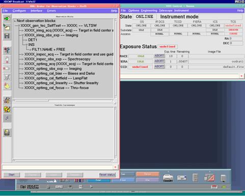
Figure 6 User Station screen #1
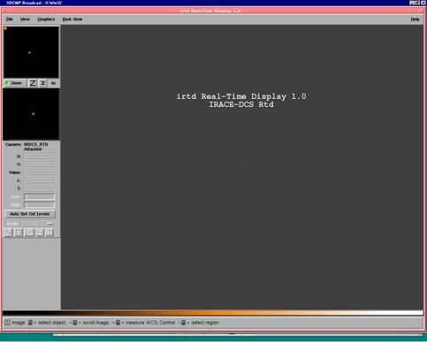
Figure 7 User Station screen #2
4.4 Observations with Templates
This is the usual way to do observations at the VLT.
In this section we
illustrate a simple example of observing run. We run the Observation Block (OB)
defined in the file XXXX_gen_tec_SelfTest.obd.
This
Normally Observation Blocks (OBs) exercise all instrument sub-systems, as well as the telescope (if declared available).
It is therefore VERY IMPORTANT to verify the status of instrument and
telescope before starting this
OBs are prepared through the P2PP tool on a separate Workstation (wxxdhs).
In order to run OBs:
1.)
Select the
2.)
Load this
3.) Press the Start button.
4.) Wait
till the
If necessary, during the execution of the
The running exposure can be aborted by pressing the Abort button in the OS Control panel.
See sections 5.15 and 8.2.3 for a more detailed description of the available templates.
No alarms are at present defined for the instrument.
|
Description |
Severity |
Operator’s
Action |
|
|
|
|
All data files used and/or generated by the Instrument Software are located under $INS_ROOT as follows:
· Configuration files:
$INS_ROOT/SYSTEM/COMMON/CONFIGFILES
· Image FITS files, results of exposures:
$INS_ROOT/SYSTEM/DETDATA
· Setup files:
$INS_ROOT/SYSTEM/COMMON/SETUPFILES/<type>
<type> is one of the following: REF, INS, DET, TARG
· Template Signature File:
$INS_ROOT/SYSTEM/COMMON/TEMPLATES/TSF
· Observation Block Description files:
$INS_ROOT/SYSTEM/COMMON/TEMPLATES/OBD
The OS Engineering GUI (see Figure 3) allows to startup/shutdown, change state and startup the stand-alone GUI of single sub-systems, e.g. whenever there are problems with specific sub-systems. To start it up:
%xxinsStart –panel OS_ENGINEERING
While the detectors and the telescope stand-alone GUIs are provided by the associated standard software packages, the ICS GUI is necessarily specific to the instrument (see Figure 8). It is based on icbpan (see [RD 26]). To start it up:
%xxinsStart –panel ICS
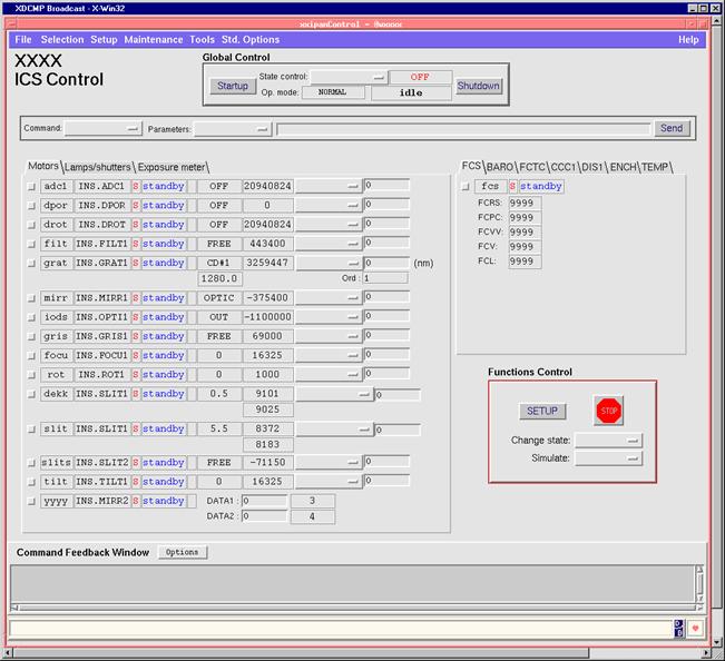
Figure 8 ICS Engineering GUI
This part of the document provides a description of the programmatic interface of the Instrument Software.
For people having no experience with
Instrumentation software yet, it is recommended, although not necessary, before
starting to read this section, first to have a look at the interactive usage of
the instrument at chapter 4 and
possibly try it out. It can help to get a better idea of how Instrumentation
software works.
XXXX defines the following modes:
· IR_IMAGING. Its purpose is to take images in the infrared.
Subsystems involved are IRACE, ICS and TCS.
· GUIDING. Its purpose is to perform guiding operations.
Subsystems involved are TCCD, ICS and TCS.
· IR_SPECTROSCOPY. Its purpose is to take spectra in the infrared.
Subsystems involved are IRACE, TCCD, ICS and TCS.
In this mode two independent exposure, one for each detector (IR and TCCD), can be executed in a semi-parallel way, i.e. the exposures on the two detectors are started at different points in time, however there is a time interval, during which both exposures are running. For more information see [RD 17].
· OPT_IMAGING. Its purpose is to take images in the optical range.
Subsystems involved are FIERA, ICS and TCS.
OS must be able to associate one or more sub-systems to each short-FITS keyword associated to a SETUP command. The filtering criteria are defined in the configuration file $INS_ROOT/SYSTEM/COMMON/CONFIGFILES/xxmcfgINS.cfg.
The table below provides a summary.
|
Subsystem |
FITS
Prefix |
|
OS |
OCS |
|
ICS |
INS |
|
IRDCS |
DET1 |
|
TCCD |
DET2 |
|
FIERA |
DET3 |
|
TCS |
TEL |
The ICS Software devices are defined in the configuration file $INS_ROOT/SYSTEM/COMMON/CONFIGFILES/xxmcfgINS.cfg:
|
# |
Name |
Description |
Positions |
Motor Axis |
FITS
Prefix |
ICB
Class |
LCU |
|
1 |
lamp |
Sample lamp |
ON/OFF |
N/A |
INS.LAMP1 |
icbLAMP |
2 |
|
2 |
tsh |
Sample shutter |
OPEN/CLOSED |
N/A |
INS.SHUT1 |
icbSHUTTER |
2 |
|
3 |
adc |
Sample ADC device |
continuous |
circular |
INS.ADC1 |
icbMOT_ADC |
1 |
|
4 |
dpor |
Sample depolarizer |
continuous |
circular |
INS.DPOR |
icbMOT_DPOR |
1 |
|
5 |
drot |
Sample derotator |
continuous |
circular |
INS.DROT |
icbMOT_DROT |
1 |
|
6 |
filt |
Sample filter wheel |
discrete |
circular |
INS.FILT1 |
icbMOT_FILTER |
1 |
|
7 |
grat |
Sample grating wheel |
continuous |
circular |
INS.GRAT1 |
icbMOT_GRATING2 |
1 |
|
8 |
mirr |
Sample mirror wheel /slide |
discrete |
circ./lin. |
INS.MIRR1 |
icbMOT_MIRROR |
1 |
|
9 |
iods |
Sample slide |
discrete |
linear |
INS.OPTI1 |
icbMOT_OPTI |
1 |
|
10 |
gris |
Sample wheel |
discrete |
circular |
INS.GRIS1 |
icbMOT_OPTI |
1 |
|
11 |
focu |
Sample slide |
continuous |
linear |
INS.FOCU1 |
icbMOT_POS |
1 |
|
12 |
rot |
Sample wheel |
continuous |
circular |
INS.ROT1 |
icbMOT_POS |
1 |
|
13 |
dekk |
Sample dekker (two jaws) |
continuous |
excentric |
INS.SLIT1.LEN |
icbMOT_SLIT2_LEN |
1 |
|
14 |
slit |
Sample slit (two jaws) |
continuous |
excentric |
INS.SLIT1.WID |
icbMOT_SLIT2_WID |
1 |
|
15 |
slits |
Sample slit wheel/slide |
discrete |
circ./lin. |
INS.SLIT2 |
icbMOT_SLITS |
1 |
|
16 |
tilt |
Sample tilt device |
continuous |
excentric |
INS.TILT1 |
icbMOT_TILT |
1 |
|
17 |
fcs |
Cryostat sensor |
N/A |
N/A |
INS.SENSOR1 |
icbSEN_ADAM |
2 |
|
18 |
baro |
Pressure sensor |
N/A |
N/A |
INS.SENSOR2 |
icbSEN_BAROMETER |
2 |
|
19 |
fctc |
Cryostat temp. sensor |
N/A |
N/A |
INS.SENSOR3 |
icbSEN_CN77000 |
2 |
|
20 |
ccc1 |
Cooling control sensor |
N/A |
N/A |
INS.SENSOR4 |
icbSEN_COOLING |
2 |
|
21 |
dis1 |
Digital sensors |
N/A |
N/A |
INS.SENSOR5 |
icbSEN_DIGITAL |
2 |
|
22 |
ench |
Humidity sensor |
N/A |
N/A |
INS.SENSOR6 |
icbSEN_HUMIDITY |
2 |
|
23 |
temp |
Temperature sensor |
N/A |
N/A |
INS.SENSOR7 |
icbSEN_ESTERS |
2 |
|
24 |
yyyy |
Sample special device |
N/A |
N/A |
INS.MIRR2 |
Special device |
2 |
Some remarks:
· All motorized devices use ESO standard motion control (Maccon) and amplifier boards.
· All motors with continuous positioning do so with a two step absolute motion to overcome possible backlash problems (see [RD 16]).
· Devices focu and rot use a linear formula for user units versus encoder units conversion.
· Devices dekk and slit have two motors each
· Device dpor rotates continuously when asked to move.
· Device adc1 uses ADC tracking mode (see [RD 16]).
· Device drot uses various tracking modes (see [RD 16]).
· Device fcs is connected to the hw device ADAM 4017 (RS-485)
· Device baro is connected to the hw device VAISALA PTB220B (RS-485)
· Device fctc is connected to the hw device OMEGA CN77000 (RS-485)
· Device ccc1 is connected to the ESO standard cabinet cooling hw device (RS-232)
· Device dis1 is connected to the ESO standard Acromag digital I/O board
· Device temp is connected to the ESO standard temperature acquisition unit Esters DC24 (RS-232).
The only special device is yyyy. It is a simple sample software device that has two double attributes in its OLDB point. These two double attributes can be set with the SETUP command (with FITS keywords INS.MIRR2.DATA1 and INS.MIRR2.DATA2). These values can be retrieved with the STATUS command.
The ICS assemblies are defined in the configuration file $INS_ROOT/SYSTEM/COMMON/CONFIGFILES/xxmcfgINS.cfg:
|
# |
Name |
Description |
Commands |
Values |
|
1 |
INS.PRESLIT |
All pre-slit devices |
STATUS |
N/A |
|
2 |
INS.INFRARED |
All devices used in the infrared arm |
STATUS |
N/A |
|
3 |
INS.OPTICAL |
All devices used in the optical arm |
STATUS |
N/A |
|
4 |
INS.MODE |
Instrument mode |
SETUP STATUS |
See 5.1 |
|
5 |
INS.PATH |
Light path |
EXPSTRT EXPEND STATUS |
INFRARED OPT_TCCD OPT_SCCD <blank> |
The Exposure types accepted are those defined by the standard IRACE, FIERA and TCCD Software packages (see respective manuals).
The OS exposure Id is a positive integer value uniquely identifying an exposure from the OS point of view.
The first SETUP command must be issued with the –expoId 0 parameter, and the Exposure Id returned by the successful completion of this command must be used for every other SETUP command, as well any other command (START, END, PAUSE, CONTINUE, ABORT, WAIT, STATUS) referring to the same exposure.
OS keeps track of the global exposure status, taking into account the current status of each detector and possible parallel exposures. It is stored in the OLDB attribute <alias>xxo:exposure.expStatus and its values are those specified by the BOSS package (see [RD 17]).
In mode IR_SPECTROSCOPY, where two detectors are involved (IRDCS and TCCD), the instrument has the same level of exposures parallelism supported by BOSS (see [RD 17]).
1. An exposure is initially defined with a SETUP command with
· -expoId 0
· INS.MODE keyword present (as part of the –function parameter or within a setup file specified with the –file parameter)
2.
A new Exposure Id is generated and returned in the
reply. Every Additional SETUP command shall contain this
3. A command START –expoId <exposure Id> will initiate the Exposure, that will go through the following phases:
a) Exposure preparation:
· OS requests TCS, through tif library call, to provide FITS information at start of the exposure
· OS sends the command START to the DCS(s) involved in the exposure
· OS sends the EXPSTRT command to ICS
Note: the default behavior of BOSS is to send first EXPSTRT to ICS and then START to DCS(s). The reversed order in XXXX has the sole purpose to provide an example of BOSS method overloading (see Appendix AA.1)
b) Exposure execution. It consists of:
q DCS Integration
q DCS Read-out
q DCS Data transfer to IWS
c) Exposure termination:
· DCS writes all image data in the FITS file, as well as some header information
· OS requests TCS, through tif library call, to provide FITS information at end of the exposure
· OS sends the EXPEND command to ICS
· OS sends the STATUS –header –dumpFits command to ICS
· OS merges the partial header files produced by OS itself, TCS, ICS and DCS in the FITS image file
· OS informs Archive (volac) that a new data file is available for archiving.
The following is an example of sequence of commands needed to define and execute exposures:
SETUP –expoId 0 –file mySetup.ref–function INS.MODE
OPT_IMAGING DET3.WIN1.UIT1 5.0
14 ß returned exposure Id
START –expoId 14
OK
WAIT –expoId 14
OK
The instrument global state is the lowest state of its sub-systems and is recorded in the OLDB attribute <alias>xxo:status.state
The table below gives the list of available states and the commands (uppercase) and/or scripts (italics) needed to change the current state.
|
To From |
OFF |
LOADED |
STAND-BY |
ON-LINE |
OFF
|
--- |
xxinsStart |
xxinsStart |
--- |
|
LOADED |
xxinsStop |
--- |
STANDBY |
ONLINE |
|
STAND-BY |
xxinsStop |
--- |
--- |
ONLINE |
|
ON-LINE |
xxinsStop |
--- |
STANDBY |
--- |
According to the standard VLT Instrumentation Software architecture, all commands to the instrument must be sent to the OS Server process xxoControl. The commands available are listed in the Command Definition Table file $INTROOT/CDT/xxoControl.cdt
In addition to the standard commands defined by BOSS, OS implements the special command TESTCMD (not in the present release).
The sole purpose of TESTCMD is to show an example how to add a command to an OS based on BOSS. See also Appendix AA.2.
None
None
The tcl class library for templates xxoseq uses the base classes provided by the standard VLT library for templates tpl (see [RD 24]). See also Appendix AA.4.
This library is registered in the BOB configuration file ($INTROOT/config/xxins.bobrc)
The Instrument Software uses several dictionaries to handle setup keywords and to create FITS files with proper header:
· ESO-VLT-DIC.CCDDCS for the keywords belonging to the TCCD sub-system
· ESO-VLT-DIC.FCDDCS for the keywords belonging to the FIERA sub-system
· ESO-VLT-DIC.IRACE for the keywords belonging to the IRDCS sub-system
· ESO-VLT-DIC.TCS for the keywords belonging to the TCS sub-system
· ESO-VLT-DIC.XXXX_ICS for the keywords belonging to the ICS sub-system
· ESO-VLT-DIC.OSB for the standard keywords belonging to the OS sub-system
· ESO-VLT-DIC.XXXX_OS for the special keywords belonging to the XXXX OS sub-system
· ESO-VLT-DIC.DPR for the keywords belonging to templates
· ESO-VLT-DIC.TPL for the keywords belonging to templates
· ESO-VLT-DIC.OBS for the keywords belonging to templates
The following dictionaries are instead not used at runtime, but for installation and/or startup purposes:
· ESO-VLT-DIC.ICB_CFG for the standard keywords belonging to the ICS configuration
· ESO-VLT-DIC.XXXX_CFG for the special keywords belonging to the instrument specific configuration
· ESO-VLT-DIC.STOO_CFG for the keywords used by the startup tool stoo
All instrument specific dictionaries are contained in module dicXXXX.
After installation, the dictionaries can be found in one of the following directories
$INS_ROOT/SYSTEM/Dictionary
$INTROOT/config
$VLTROOT/config
No alias file is used.
After installation, all configuration files used by the Instrument Software are located in the directory $INS_ROOT/SYSTEM/COMMON/CONFIGFILES.
See chapter 6 for more detailed information on the contents of the individual files.
OS treats these keywords. The instrument does not implement any special OCS keyword: it uses only standard keywords defined by the BOSS package (see [RD 17]) and described in the dictionary ESO-VLT-DIC.OSB.
OS and ICS treat these keywords.
The table below shows the keywords used:
|
Setup
keyword |
Device |
Units |
Description |
Values |
|
INS.MODE |
(assembly) |
N/A |
Instrument mode |
See 5.1 |
|
INS.LAMP1.ST |
lamp |
N/A |
Turn ON/OFF |
T/F |
|
INS.SHUT1.ST |
tsh |
N/A |
OPEN/CLOSE |
T/F |
|
INS.ADC1.MODE |
adc |
N/A |
ADC mode |
OFF/AUTO |
|
INS.DPOR.ST |
dpor |
N/A |
Start/Stop continuous rotation |
T/F |
|
INS.DROT.RA INS.DROT.DEC INS.DROT.POSANG INS.DROT.MODE INS.DROT.STATINDX |
drot |
hhmmss.mm ddmmss.mm deg none none |
Right Ascension Declination Start position angle Derotator mode Offset index for STAT mode |
0-360 STAT/SKY/ELEV See xxmcfgINS.cfg |
|
INS.FILT1.NAME |
filt |
N/A |
Filter name |
See xxmcfgINS.cfg |
|
INS.GRAT1.NAME INS.GRAT1.WLEN |
grat |
N/A nm |
Grating name Central wavelength |
See xxmcfgINS.cfg |
|
INS.MIRR1.NAME |
mirr |
N/A |
Mirror name |
See xxmcfgINS.cfg |
|
INS.OPTI1.NAME |
iods |
N/A |
Slide position name |
See xxmcfgINS.cfg |
|
INS.GRIS1.NAME |
gris |
N/A |
Slide position name |
See xxmcfgINS.cfg |
|
INS.FOCU2.POS |
focu |
mm |
Focus position |
See xxmcfgINS.cfg |
|
INS.ROT1.POS |
rot |
deg |
Position angle |
See xxmcfgINS.cfg |
|
INS.SLIT1.LEN |
dekk |
mm |
Decker length |
See xxmcfgINS.cfg |
|
INS.SLIT1.WID |
slit |
mm |
Slit width |
See xxmcfgINS.cfg |
|
INS.SLIT2.NAME |
slits |
N/A. |
Position name |
See xxmcfgINS.cfg |
|
INS.TILT1.POS |
tilt |
micron |
Tilt position |
See xxmcfgINS.cfg |
|
INS.MIRR2.DATA1 INS.MIRR2.DATA2 |
yyyy |
mm deg |
Sample special device setup keyw. Sample special device setup keyw. |
any float number any float number |
Remarks:
· All motorized devices with encoder can also be addressed to a specific absolute or relative encoder value using the keywords .ENC and .ENCREL (e.g. INS.FILT1.ENC 15000 or INS.FILT1.ENCREL 1000). The usage of these keywords is however limited to engineering/maintenance operations.
OS and DCS treat these keywords.
The instrument does not implement any special DCS keyword: it uses only keywords defined by the standard DCS packages IRACE (see [RD 15]), FIERA (see [RD 14]) and CCD (see [RD 13]).
Images, as result of exposures, are written on WS disk in FITS format (see [AD 01]).
An example of complete FITS header is given in 11.8.1
The VLT on-line Archive is informed of each new complete file ready for archiving, according to the standard protocol defined in [AD 08].
5.13 Public on-line database attributes
This section is applicable only to those
instruments, which are supposed to work in conjunction with other instruments
(e.g. through Super-OS).
No OLDB attribute is publicly available.
An example of operational log in FITS format is given in 11.9.1.
This section describes briefly the templates implemented for the instrument.
· XXXX_irimg_acq. It is the acquisition template for the IR_IMAGING Mode.
· XXXX_irspec_acq. It is the acquisition template for the IR_SPECTROSCOPY Mode.
· XXXX_optimg_acq. It is the acquisition template for the OPT_IMAGING Mode.
· XXXX_optimg_cal_bias. It executes bias exposures with the FIERA DCS in OPT_IMAGING Mode
· XXXX_optimg_cal_flatfield. It executed flat field exposures with the FIERA DCS in OPT_IMAGING Mode
· XXXX_optimg_cal_focus. It checks the FIERA camera focus in OPT_IMAGING Mode
· XXXX_optimg_cal_linearity. It does a CCD chip linearity check with the FIERA DCS in OPT_IMAGING Mode
· XXXX_irimg_obs_exp. It performs standard exposures in IR_IMAGING Mode
· XXXX_irspec_obs_exp. It performs standard exposures in IR_SPECTROSCOPY Mode
· XXXX_optimg_obs_exp. It performs standard exposures in OPT_IMAGING Mode
This section is reserved to engineers responsible of the
instrument maintenance.
It describes where
instrument configuration parameters are stored and the way, in which they can
be changed, saved and kept under configuration control.
The instrument
configuration is based on the Configuration Tool (ctoo, see User Manual [RD 25]).
In order to be able
to operate the instrument properly and reliably, the instrument configuration
parameters must be kept under configuration control. For this reason, all files containing configuration
parameter values for the final target are put in one single dedicated cmm module, called xxmcfg (directory config).
After installation,
all configuration files are located in $INS_ROOT/SYSTEM/COMMON/CONFIGFILES,
except IRACE configuration and clock files, located under
$INS_ROOT/SYSTEM/MISC/IRACE.
The files
containing information related to the instrument configuration are:
·
xxmcfgCONFIG.cfg. It is the master
file for the ctoo tool and contains
basic information about which other files are involved and for what purpose.
·
xxmcfgINS.cfg. It contains most
of the Instrument configuration information.
·
xxmcfgSTART.cfg. It contains only
the startup information (e.g. which subsystems are available and at which level
of simulation they should work) and is used by xxinsStartup, xxinsStart
and xxinsStop, all based on the
Startup Tool stoo (see [RD 19]).
·
xxmcfgTARGET.cfg. It contains
the configuration information for a specific target (e.g. for the VLT Control
Model).
·
xxmcfgTEST.cfg. It contains
the configuration information for running self test scripts (see manual page of
inscSelfTest)
·
xxmcfg*M.dbcfg. Each of these
files contains the configuration of one motor controlled by ICS. They have been
created using the VLT Motor Engineering Interface Tool (motei, see [RD 06]).
·
Other *.cfg and *.dbcfg files are created and used by
the standard DCS and Real-Time Display (rtd/irtd) packages.
6.1 Change Instrument Configuration Parameters
For configuration changes to take effect, they have to be applied to the files stored in the $INS_ROOT.
Once a new stable configuration has been found, this configuration has to be stored in the xxmcfg module, as this is the only way to save permanently any change to the instrument configuration.
The accepted sequence of operations, which allow keeping control over changes to the instrument configuration, is:
1. Edit the files in the $INS_ROOT, that contain the parameters to be modified:
· use motei for the xxmcfg*M.dbcfg files
· use a normal text editor for the *.cfg files (they are ASCII files in PAF format).
2. If the changes done affect ICS LCU devices, run:
% icbConfigSet XXXX
3. Test the Instrument in the new configuration
4. Repeat the steps above as many times as needed.
a) The configuration changes are rejected.
Re-install the latest well-known configuration stored in the xxmcfg module:
% cmmCopy xxmcfg
% cd xxmcfg/src
% make clean all man install
% icbConfigSet XXXX
b) The configuration changes are accepted:
Archive the new configuration in the xxmcfg module:
% ctooConfigArchive XXXX
ctooConfigArchive (should be accessible also from a GUI menu) executes the following steps:
· cmmModify xxmcfg
· copy the configuration files from $INS_ROOT to the xxmcfg module (as specified by the CONFIG.ARCHIVE.* keywords, see [RD 25]).
· cmmArchive xxmcfg
When a complete software (re-)installation on the IWS is going to be done, a snapshot of the current instrument configuration (as described above in point 5b) MUST be archived before starting the new installation.
As specified in
[AD 06], an Instrument
Software package must include test procedures and scripts to exercise the
Instrument functionality and perform automatic regression tests.
The set of procedures and scripts used is described in detail in [RD 27]. They are based on the standard test scheme supported by the Instrumentation Common Software (see [AD 07]).
The automatic regression tests are based on the
standard Tool for Automated Testing (tat,
see [RD 28]).
8 MAINTENANCE
This module is dedicated to the installation of the instrument software on the final target.
· src
· xxinsStartup. Script used to startup the instrument software after a rebuild or some major modifications to the hw configuration (panel pops-up allowing to configure the simulation levels).
· xxinsStart. Script normally used to startup the whole instrument software or sub-systems. Simulation levels are kept as defined in the configuration files xxmcfgSTART.cfg.
· xxinsStop. Script normally used to stop the whole instrument software or sub-systems.
· ENVIRONMENTS
· lxxics1. Template directory to be taken by pkginBuild when building environment lxxics1
· lxxics2. Template directory to be taken by pkginBuild when building environment lxxics2
· lxxtccd. Template directory to be taken by pkginBuild when building environment lxxtccd
· wxxxx. Template directory to be taken by pkginBuild when building environment wxxxx
· wxxtcs. Template directory to be taken by pkginBuild when building environment wxxtcs
· config
· xxins.bobrc. Configuration file for BOB
· xxins-misc-all.env. File containing environment variable definitions, sourced automatically at login (if CDE used)
· xxinsINSTALL.cfg. Main configuration file for pkginBuild. It includes:
· xxinsINSTALL_TCSSIM.cfg. It contains definitions to be used only for targets where the TCS simulation package is used.
· xxinsINSTALL_VLTSW.$VLTSW_RELEASE cfg. It contains definitions related to versions of modules different to those delivered with the VLT Software release specified in $VLTSW_RELEASE
This module contains the instrument specific dictionaries.
· src
· dicXXXX_CFG.txt. It contains configuration keywords used in xxmcfgINS.cfg for the special device yyyy.
· dicXXXX_ICS.txt. It contains run-time keywords used by ICS
· dicXXXX_OS.txt. It contains run-time keywords used by OS
This module contains the code for the OS processes.
· src
· xxoControl.C It contains the main of the OS front-end process xxoControl.
· xxoSERVER.C. It contains the code for class xxoSERVER, sub-class of bossSERVER. In particular, method SubsystemInterfaces creates instances of the proper interface class for each sub-system used by OS.
· xxoExpoCtrl.C. It contains the overloading of bossSERVER methods StartPostProc and StartPostProc. They are just examples of bossSERVER method overloading.
· include
· xxoErrors.h. It defines macros for the module errors
· xxoPrivate.h. It contains definitions used by xxoControl
· xxoSERVER.h. It contains definitions for the class xxoSERVER
· CDT
· xxoControl.cdt Command Definition Table for the process xxoControl
· ERRORS
· xxo_ERRORS Definition of errors for this module
· config
· xxoTccd.det Detector Setup File used for instrument mode GUIDING
· dbl
· xxoSERVER.class. dbl class defining the branches for the sub-systems used.
· xxo.db. dbl include file defining the whole OS branch of the OLDB. This file must be included in wxxxx/dbl/DATABASE.db
8.2.2 Module xxopan
This module contains the code for the OS GUIs.
· src
· xxopanControl.pan File created with the VLT panel editor for the OS Control GUI (see Figure 5)
· xxopanControl.doc. Source file for the panel xxopanControl manual page
· xxopanStatus.pan File created with the VLT panel editor for the OS Status GUI. Dummy.
· xxopanStatus.pan. Source file for the panel xxopanStatus manual page
· xxopanEngineering.pan. File created with the VLT panel editor for the OS Engineering GUI (see Figure 3)
· xxopanEngineering.pan. Source file for the panel xxopanEngineering manual page
· library xxopanPrivate
· xxopanMisc.tcl. It contains miscellaneous procedure used within OS GUI panels.
· xxopanStateSubSystems_uifClass.tcl. VLT panel editor class used within xxopanEngineering. It contains:
· xxopanStateIcs_uifClass.tcl. VLT panel editor class used to act on ICS
· xxopanStateIrDcs_uifClass.tcl VLT panel editor class used to act on IRDCS
· xxopanStateOs_uifClass.tcl VLT panel editor class used to act on xxoControl
· xxopanStateTccd_uifClass.tcl VLT panel editor class used to act on TCCD
· xxopanStateFiera_uifClass.tcl VLT panel editor class used to act on FIERA
· xxopanStateTcs_uifClass.tcl VLT panel editor class used to act on VLTISIM
This module contains the files contributing to the Instrument Package, needed by the DFS, and in particular P2PP.
· src
The VLT utility oslxCompileTsf is used by make to generate the .tsf files (directory config) from the tsfx files.
· XXXX_irimg_acq.tsfx. TSF source file for Target Acquisition in IR_IMAGING mode
· XXXX_irimg_obs_exp.tsfx. TSF source file for standard observations in IR_IMAGING mode
· XXXX_irspec_acq.tsfx. TSF source file for Target Acquisition in IR_SPECTROSCOPY mode
· XXXX_irspec_obs_exp.tsfx. TSF source file for standard observations in IR_SPECTROSCOPY mode
· XXXX_optimg_acq.tsfx. TSF source file for Target Acquisition in OPT_IMAGING mode
· XXXX_optimg_cal_bias.tsfx. TSF source file for bias exposures in OPT_IMAGING mode
· XXXX_optimg_cal_flatfield.tsfx. TSF source file for flat field exposures in OPT_IMAGING mode
· XXXX_optimg_cal_focus.tsfx. TSF source file for focus check in OPT_IMAGING mode
· XXXX_optimg_cal_linearity.tsfx. TSF source file for linearity check in OPT_IMAGING mode
· XXXX_optimg_obs_exp.tsfx. TSF source file for standard observations in OPT_IMAGING mode
· config
· XXXX.isf Instrument Summary File, to be included in the Instrument Package for P2PP
· include
· xxotsfDET_EXPLEVEL.tsfx. TSF include file. It contains the following keywords:
DET.EXPLEVEL
· xxotsfINS_FILT.tsfx. TSF include file. It contains the following keywords:
INS.FILT1.NAME
· xxotsfINS_MODE.tsfx. TSF include file. It contains the following keywords:
INS.MODE
· xxotsfIRDET.tsfx. TSF include file. It contains DET1 keywords for IRDCS and includes:
· xxotsfIRDET_DIT.tsfx. TSF include file. It contains the following keywords:
DET1.DIT
DET1.NDIT
· xxotsfSCCD.tsfx. TSF include file. It contains DET3 keywords for FIERA and includes:
DET3.WIN1.ST
DET3.WIN1.STRX
DET3.WIN1.STRY
DET3.WIN1.NX
DET3.WIN1.NY
· xxotsfISCCD_BIN.tsfx. TSF include file. It contains the following keywords:
DET3.WIN1.BINX
DET3.WIN1.BINY
· xxotsfISCCD_DIT.tsfx. TSF include file. It contains the following keywords:
DET3.WIN1.UIT1
· xxotsfISCCD_DIT_LIST.tsfx. TSF include file. It contains the following keywords:
DET3.WIN1.UIT1
· xxotsfISEQ.tsfx. TSF include file. It contains the following keywords:
SEQ.NEXPO
· xxotsfITCCD_DIT.tsfx. TSF include file. It contains the following keywords:
DET2.WIN1.UIT1
· xxotsfITEL.tsfx. TSF include file. It contains the following keywords:
TEL.PRESET.NEW
TEL.TARG.ALPHA
TEL.TARG.DELTA
TEL.TARG.EQUINOX
TEL.TARG.OFFANGLE
TEL.TARG.ADDVELALPHA
TEL.TARG.ADDVELDELTA
TEL.TARG.PMA
TEL.TARG.PMD
TEL.GS1.ALPHA
TEL.GS1.DELTA
TEL.GS1.MAG
This module contains the Template Script files, as well as the Reference Setup files used by Templates and test OBs.
· src
· XXXX_acq.seq. Template Script file used by acquisition templates in IR_IMAGING and OPT_IMAGING mode
· XXXX_irimg_obs_exp.seq. Template Script file used by standard observation templates in IR_IMAGING mode
· XXXX_irspec_acq.seq. Template Script file used by acquisition templates in IR_SPECTROSCOPY mode
· XXXX_irspec_obs_exp.seq. Template Script file used by standard observation templates in IR_SPECTROSCOPY mode
· XXXX_optimg_cal_bias.seq. Template Script file used by bias template in OPT_IMAGING mode
· XXXX_optimg_cal_flatfield.seq. Template Script file used by flat field template in OPT_IMAGING mode
· XXXX_optimg_cal_focus.seq. Template Script file used by focus check template in OPT_IMAGING mode
· XXXX_optimg_cal_linearity.seq. Template Script file used by linearity check template in OPT_IMAGING mode
· XXXX_optimg_obs_exp.seq. Template Script file used by standard observation templates in OPT_IMAGING mode
· xxoseqGenTecSelfTest.txt. Used in the Makefile to build the self test obd XXXX_gen_tec_SelfTest.obd and store it in the directory config.
· xxoseqTsfList.txt. Used in the Makefile to build the test OBs for each individual template and store them in the directory config.
· library xxoseq
· xxoseqICS.tcl. Defines methods for the itcl class xxoseqICS, sub-class of tplICS
· config
· XXXX_acq.ref Reference Setup File used in acquisition templates in IR_IMAGING and OPT_IMAGING mode
· XXXX_irimg_obs_exp.ref. Reference Setup File used by standard observation templates in IR_IMAGING mode
· XXXX_irspec_acq.ref. Reference Setup File used by acquisition templates in IR_SPECTROSCOPY mode
· XXXX_irspec_obs_exp.ref. Reference Setup File used by standard observation templates in IR_SPECTROSCOPY mode
· XXXX_optimg_cal_bias.ref. Reference Setup File used by bias template in OPT_IMAGING mode
· XXXX_optimg_cal_flatfield.ref. Reference Setup File used by flat field template in OPT_IMAGING mode
· XXXX_optimg_cal_focus.ref. Reference Setup File used by focus check template in OPT_IMAGING mode
· XXXX_optimg_cal_linearity.ref. Reference Setup File used by linearity check template in OPT_IMAGING mode
· XXXX_optimg_obs_exp.ref. Reference Setup File used by standard observation templates in OPT_IMAGING mode
· XXXX_gen_tec_SelfTest.obd. OB Description File to test all templates
· XXXX_irimg_acq.obd OB Description File to test template XXXX_irimg_acq
· XXXX_irimg_obs_exp.obd OB Description File to test template XXXX_irimg_obs_exp
· XXXX_irspec_acq.obd OB Description File to test template XXXX_irspec_acq
· XXXX_irspec_obs_exp.obd OB Description File to test template XXXX_irspec_obs_exp
· XXXX_optimg_acq.obd OB Description File to test template XXXX_optimg_acq
· XXXX_optimg_cal_bias.obd OB Description File to test template XXXX_optimg_cal_bias
· XXXX_optimg_cal_flatfield.obd OB Description File to test template XXXX_optimg_cal_flatfield
· XXXX_optimg_cal_focus.obd OB Description File to test template XXXX_optimg_cal_focus
· XXXX_optimg_cal_linearity.obd OB Description File to test template XXXX_optimg_cal_linearity
· XXXX_optimg_obs_exp.obd OB Description File to test template XXXX_optimg_obs_exp
It contains the code and files for ICS WS part.
· src
· xxiConfigSet.tcl. Tcl script called by icbConfigSet to set the yyyy special device configuration values in the ICS LCU 2 OLDB (file $VLTDATA/config/lxxics2.dbcfg)
· xxiControl.C It contains the main for the ICS WS front-end process xxiControl
· xxiCtrlMAIN_HANDLER.C It contains the code for the class xxiCtrlMAIN_HANDLER, sub-class of ic0CtrlMAIN_HANDLER. It overloads the method NewServer, needed in order to create an instance of class xxiSERVER
· xxiSERVER.C. It contains the code for the class xxiSERVER, sub-class of ic0SERVER. It overloads, just as as example, the method StatusCB, callback for the command STATUS, and also the methods related to OLDB events (AttachDbEvents, DbEvtCB) and timers (AddTimers, TimerCB). The code overloading ic0 methods is here only to provide examples to developers. They should be removed when building a new instrument from the Template Instrument code.
· xxi_LAMP.C. It contains the code for the class xxi_LAMP, sub-class of ic0INS_LAMP, to provide an example of standard device class overloading. It should be deleted when building a new instrument from the Template Instrument code.
· xxiINS_ANALOG.C It contains the code for the class xxiINS_ANALOG, sub-class of ic0INS_DEVICE, for the special device yyyy. In particular, it overloads method DevTrigger. It should be deleted when building a new instrument from the Template Instrument code.
· xxins_TRAK.C. It contains the code for the class xxins_TRAK, sub-class of ic0INS_ASSEMBLY, to provide an example of assembly class overloading. It should be deleted when building a new instrument from the Template Instrument code.
· include
· xxiControl.h. Definition of classes to be used for the ICS devices on the WS.
· xxiCtrMAIN_HANDLER.h Declaration of the class xxiMAIN_HANDLER
· xxiSERVER.h Declaration of the class xxiSERVER
· xxins_LAMP.h Declaration of the class xxins_LAMP.
· xxiINS_ANALOG.h Declaration of the class xxiINS_ANALOG
· xxiINS_TRAK.h Declaration of the class xxiINS_TRAK
· CDT
· xxiControl.cdt Command Definition Table for the WS ICS front-end process xxiControl
· xxiSimControl.cdt. Command Definition Table for the ICS LCU simulation process xxiSimControl
· config
· lxxics1.scan. Scan configuration file for the ICS LCU 1
· lxxics2.scan. Scan configuration file for the ICS LCU 2
· dbl
· xxiSIM_CONTROL.class. dbl class containing the OLDB branch used by xxiSimControl
· xxiEnv1.db. dbl include file for the ICS LCU 1 and WS
· xxiEnv2.db. dbl include file for the ICS LCU 2 and WS
· xxiHISTORIAN.db. dbl include file which defines the CCS historian tables used by ICS
· xxiEnv.db. dbl include file which creates the whole ICS branch on WS and LCU
This module contains the code for the ICS GUIs.
· src
· xxipanControl.pan ICS stand-alone panel, created with the CCS panel editor
· xxipanControl.doc Manual page for the xxipanControl panel
It contains the code and files for ICS LCU part, in particular the yyyy special device.
· src
· xxidev.boot Boot file for the xxidev module, as requested by LCC
· xxidevDeviceCmds.c. It contains the callbacks for all implemented commands, as requested by icb
· xxidevDeviceDummies.c. It contains the dummy callbacks for commands not implemented.
· xxidevDeviceNewObj.c It contains constructor and destructor of a special device object
· xxidevServer.c It contains the code of the yyyy server task, as requested by icb
· xxidevServerInterface.c It contains the interface functions defined in the Command Interpreter Table file xxidevServer.cit
· xxidevVersion.c. It contains the function which returns the version of the module
· xxidevFocuInitSw.c. It contains an example of code for the sw init hook function provided by ic0. It should be deleted when building a new instrument from the Template Instrument code.
· xxidevFocuPreInit.c. It contains an example of code for the pre hw init hook function provided by ic0. It should be deleted when building a new instrument from the Template Instrument code.
· xxidevFocuPostInit.c. It contains an example of code for the post hw init hook function provided by ic0. It should be deleted when building a new instrument from the Template Instrument code.
· xxidevFocuPreMove.c. It contains an example of code for the pre move hook function provided by ic0. It should be deleted when building a new instrument from the Template Instrument code.
· xxidevFocuPostMove.c. It contains an example of code for the post move hook function provided by ic0. It should be deleted when building a new instrument from the Template Instrument code.
· xxidevFocuUsr2Enc.c. It contains an example of code for the user units conversion hook function provided by ic0. It should be deleted when building a new instrument from the Template Instrument code.
· CDT
· xxidevServer.cdt Command Definition Table for the process xxidevServer
· CIT
· xxidevServer.cit Command Interpreter Table for the process xxidevServer
· ERRORS
· xxidev_ERRORS. It contains error definitions used in this module
· dbl
· xxidevYYYY.db dbl include file adding the OLDB point for the device yyyy. It is included in xxiEnv2.db
· include
· xxidevErrors.h It contains macros for errors used in this module
· vnidevDevice.h. It contains definitions used by the device yyyy
· xxidevServer.h It contains function declarations used in the xxidevServer process
Engineering/Maintenance Operations on DCS sub-systems can be performed through the standard stand-alone GUIs:
· TCCD
%xxinsStart –panel TCCD
· FIERA
%xxinsStart –panel FIERA
· IRDCS
%xxinsStart –panel IRDCS
· XXXX_optimg_tec_parasitic. It is the used to detect light leaks inside the instrument.
This module contain the files describing the current configuration of the instrument
· config
· xxmcfgCONFIG.cfg. Main configuration file used by the VLT tool ctoo
· xxmcfgINS.cfg It contains most of the instrument configuration, except the startup/simulation part
· xxmcfgSTART.cfg It contains the startup/simulation part of the instrument configuration
· xxmcfgTARGET.cfg. It is an empty file to provide a hook for target specific definitions
· xxmcfgTEST.cfg. It contains all definitions needed to run test scripts (see inscSelfTest)
· xxmcfgIRDCS.cfg. It contains the IRDCS part of the instrument configuration
· xxmcfgADC1M.dbcfg. OLDB backup file, created by motei, containing the configuration of the ADC1 motor
· xxmcfgDEKK1M.dbcfg. OLDB backup file, created by motei, containing the configuration of the DEKK1 motor
· xxmcfgDEKK2M.dbcfg. OLDB backup file, created by motei, containing the configuration of the DEKK2 motor
· xxmcfgDPORM.dbcfg. OLDB backup file, created by motei, containing the configuration of the DPOR motor
· xxmcfgDROTM.dbcfg. OLDB backup file, created by motei, containing the configuration of the DROT motor
· xxmcfgFILTM.dbcfg. OLDB backup file, created by motei, containing the configuration of the FILT motor
· xxmcfgFOCUM.dbcfg. OLDB backup file, created by motei, containing the configuration of the FOCU motor
· xxmcfgGRATM.dbcfg. OLDB backup file, created by motei, containing the configuration of the GRAT motor
· xxmcfgGRISM.dbcfg. OLDB backup file, created by motei, containing the configuration of the GRIS motor
· xxmcfgIODSM.dbcfg. OLDB backup file, created by motei, containing the configuration of the IODS motor
· xxmcfgMIRRM.dbcfg. OLDB backup file, created by motei, containing the configuration of the MIRR motor
· xxmcfgROTM.dbcfg. OLDB backup file, created by motei, containing the configuration of the ROT motor
· xxmcfgSLIT1M.dbcfg. OLDB backup file, created by motei, containing the configuration of the SLIT1 motor
· xxmcfgSLIT2M.dbcfg. OLDB backup file, created by motei, containing the configuration of the SLIT2 motor
· xxmcfgSLITSM.dbcfg. OLDB backup file, created by motei, containing the configuration of the SLITS motor
· xxmcfgTILTM.dbcfg. OLDB backup file, created by motei, containing the configuration of the TILT motor
· xxmcfgIcsSelfTest_*.ins. Instrument setup files used by inscSelfTest as the ICS self-test procedure
This module contains the maintenance Template Script files, as well as the Reference Setup files used by Templates and test OBs.
· src
· xxmseqGenTecMSSelfTest.txt. Used in the Makefile to build the self test obd XXXX_gen_tec_MSTest.obd and store it in the directory config.
· xxmseqTsfList.txt. Used in the Makefile to build the test OBs for each individual template and store them in the directory config.
· config
· XXXX_optimg_tec_parasitic.ref Reference Setup File used in the parasitic charge measurements template
This module contains the files contributing to the Instrument Package, needed by the DFS, and in particular P2PP.
· src
The VLT utility oslxCompileTsf is used by make to generate the .tsf files (directory config) from the tsfx files.
· XXXX_optimg_tec_parasitic.tsfx. TSF source file for parasitic charge measurement template
· config
· XXXX_tec.isf Maintenance Instrument Summary File, to be included in the Maintenance Instrument Package for P2PP
All suggestions presented in this chapter aim to allow the user to solve themselves the most common problems they may encounter.
In all cases, it is recommended to use the utility logMonitor to look for detailed reasons of the failure.
9.1 Problems at System Start-up
1. Make sure that the terminal is booting from the right host (wxxxx)
2. Make sure you have entered the right user name (xxxx) and password.
1. Make sure you issued the command from a xterm running on the Instrument Workstation (wxxx) as user xxxx. Type:
%whoami
2. Check the Start-up configuration (file xxmcfgSTART.cfg).
9.1.3 Start-up of control processes fails
1. Start the OS Engineering GUI:
%xxinsStart –panel OS_ENGINEERING
2. Make sure that the sub-system associated to the failing process is supposed to run at a simulation level compatible with the hw available (cross-check also with the contents of the file xxmcfgSTART.cfg).
3. If the failure is related to the LCU sw (e.g. LCU not responding), a reboot of the LCU may help.
9.1.4 xxiControl starts with a wrong simulation level
1. The simulation level at which xxiControl is supposed to start is specified by the keyword INS.CON.OPMODE, defined in xxmcfgSTART.cfg (NOT in xxmcfgINS.cfg !!).
9.1.5 TCCD starts with a wrong simulation level and fails to go STANDBY
1. If the TCCD LCU is available, but no TCCD system is connected to it, xxmcfgSTART.cfg should contain:
OCS.DET2.SWSIM "HW_SIM”
9.1.6 xxoControl tries to access sub-systems declared as not available
1. Information about availability of sub-systems is provided through the keywords OCS.*.ACCESS in the file xxmcfgSTART.cfg.
1. Start the OS Engineering GUI:
%xxinsStart –panel OS_ENGINEERING
2. Check which sub-system failed to go online
3. Start the related stand-alone panel
4. If the failing sub-system is ICS, the most common case is that one of its devices has been disconnected (e.g. one motor) or set to handset/manual mode (e.g. one lamp or shutter). The failing device can be immediately recognized because its state is NOT online.
· Check the hardware connections/hardware switches
· Try to re-initialize the device.
5. If the failing sub-system is TCCD, the most common case is that the connection to the ACE box is down
· Check all cables in particular the fiber optics cable.
6. If the failing sub-system is FIERA, the most common case is that the controller is powered off (e.g. because of overheating protections).
7. If the failing sub-system is IRACE, the most common case is that the WS part tries to access the Sparc, whereby this computer is not available. Check the definition of environment variables, in particular SDMA_HOST (it must be the host name of the IWS, when the Sparc is not available).
9.2 Problems when running exposures
9.2.1 Cannot send commands to TCS or access tif
1. Make sure that TCS is running and ONLINE.
2. Make sure that TCS RA and DEC are OK. If the RA and DEC background color in the OS Control Panel is gray, then probably TCS is not operational. See also 4.1.2.
9.2.2 Templates cannot access Midas
1. Make sure that MIDAS NOV99 or higher is installed on the IWS. If not, disable MIDAS access from templates (see 4.1.3)
The Instrument Software uses the standard mechanism defined and provided by the CCS error system to log and return error information, both at functional and command level, on LCU and WS.
Errors are defined in the following files:
· xxoErrors.h OS error codes
· xxo_ERRORS OS error messages
See also section 11.11
11.1.1 Command Definition Table for program xxoControl
//*****************************************************************************
//
E.S.O. - VLT project
//
//
"@(#) $Id: xxoControl.cdt,v 1.47 2003/03/21 16:18:07 vltsccm Exp $"
//
//
who when what
//
---------- --------
----------------------------------------------
//
gzins 28/11/99 Created
//
epozna adopted fpr boss
//
epozna use common interface
(osb)
//
epozna 10/10/00 remove colons after PUBLIC_COMMANDS
//************************************************************************
// NAME
// xxoServer.cdt - command definition table
//
// DESCRIPTION
// This file describes the standard commands
defined in a process
// xxoServer (Supervisory Observation Software
server).
//
//------------------------------------------------------------------------
//
//************************************************************************
PUBLIC_COMMANDS
//------------------------------------------------------------------------
// BOSS Common Commands
//********************************************************************
//********************************************************************
//
#include
"osbControl.cdt"
xxinsStartup
NAME
xxinsStartup - configure and start XXXX
main application
SYNOPSIS
xxinsStartup
DESCRIPTION
This script starts the XXXX startup
configuration panel
and then starts XXXX if the START button is
pressed.
The user can set several options in the
startup panel
before starting XXXX:
Telescope (TCS):
- Available: select if the telescope can
be accessed or not.
Instrument (ICS):
- Available: normally true.
- WS Simulation: normally false, unless the instrument
is not available.
- User Interface: start the ICS
stand-alone panel.
Detectors (DCS):
- Available: normally true; set to false, if the
detector should not be
used.
- WS Simulation: normally false; set to true, if the
detector hardware is not
available.
- User Interface: start the detector
stand-alone panel.
- Start RTD: start the detector RTD.
Miscelaneous:
- Start BOB: start the BOB panel, normally true.
- Start OS Control: start the OS control
panel.
- Start Alarm Display: start the alarm
display.
FILES
xxmcfgSTART.cfg start configuration file
xxmcfgINS.cfg instrument configuration file
Both are in
$INS_ROOT/SYSTEM/COMMON/CONFIGFILES
EXAMPLES
xxinsStartup
SEE ALSO
xxinsStart xxinsStop
###
generated by docDeroff ###
xxinsStart
NAME
xxinsStart - start XXXX application
SYNOPSIS
xxinsStart [-log] [-proc <appl>]
[-panel <panel>]
[-restart] [-loglevel <n>]
DESCRIPTION
This script starts the XXXX application.
- Default panels are stopped.
- All subsystems are started.
- The Observation Software is started.
- Default panels are started.
Options:
no option: Check that OS and its subsystems are
running,
start them if necessary.
Restart default panels.
-proc <name> Start the application <name>.
<name> may be the
name of a subsystem
(e.g. ICS) or OS.
To obtain a list of known
panels, use e.g.:
'xxinsStart -proc show'
-panel <name> Start the panel <name>.
To obtain a list of known
panels, use e.g.:
'xxinsStart -panel show'
Option modifiers:
-restart Restart the application.
OS and subsystems are
stopped, then restarted.
Only default panels are
stopped and restarted.
-log Open a log window
(-log MUST always be the
first option).
To suppress the log window, pass
any other
option to xxinsStart, e.g.
'-loglevel 1'.
-loglevel <n> Increase logging for debugging. n = 0..3.
FILES
xxmcfgSTART.cfg start configuration file
xxmcfgINS.cfg instrument configuration file
Both are in
$INS_ROOT/SYSTEM/COMMON/CONFIGFILES
EXAMPLES
xxinsStart -panel OS_CONTROL
SEE ALSO
xxinsStop
###
generated by docDeroff ###
xxinsStop
NAME
xxinsStop - stop XXXX application
SYNOPSIS
xxinsStop [-log] [-proc <appl>]
[-panel <panel>]
[-standby] [-loglevel <n>]
DESCRIPTION
This script stops the XXXX application.
- OS is placed in state STANDBY.
- All panels are stopped.
- OS and all subsystems are stopped.
Options:
no option: Place OS in state STANDBY, stop all
panels
and stop OS and all
subsystems.
-proc <name> Stop the application <name>.
<name> may be the
name of a subsystem
(e.g. ICS) or OS.
To obtain a list of known
panels, use e.g.:
'xxinsStop -proc show'
-panel <name> Stop the panel <name>.
To obtain a list of known
panels, use e.g.:
'xxinsStop -panel show'
-standby Only place OS in state STANDBY.
Leave all panels and
processes running.
Option modifiers:
-log Open a log window
(-log MUST always be the
first option).
To suppress the log window,
pass any other
option to xxinsStop, e.g.
'-loglevel 1'.
-loglevel <n> Increase logging for debugging. n = 0..3.
FILES
xxmcfgSTART.cfg start configuration file
xxmcfgINS.cfg instrument configuration file
Both are in
$INS_ROOT/SYSTEM/COMMON/CONFIGFILES
EXAMPLES
xxinsStop -panel OS_CONTROL
SEE ALSO
xxinsStart
###
generated by docDeroff ###
All include files are private to the instrument.
The library xxoseq provides classes used for the development of XXXX Templates. The man-pages presented in this section refer to classes belonging to that library.
xxoseqICS
NAME
xxoseqICS - XXXX ICS interface for
templates.
SYNOPSIS
xxoseqICS ics
DESCRIPTION
XXXX
ICS interface for BOB templates.
PARENT
tplICS
PUBLIC METHODS
see tplICS man page.
SEE ALSO
tplICS
###
generated by docDeroff ###
The configuration
files (see Chapter 6), due to their size, are not shown here.
11.6.1 Example of Reference Setup file
TBD
11.6.2 Example of Instrument Setup File
#******************************************************************************
# E.S.O.
- VLT project
#
#
"@(#) $Id: xxmcfgIcsSelfTest_1.ins,v 1.64 2003/02/25 12:03:27 vltsccm Exp
$"
#
#
who when what
#
---------- --------
----------------------------------------------
#
rschmutz 13/05/02 SLIT1 param. adjusted (were just out of
range).
#
alongino 04/01/01 created
#
#************************************************************************
PAF.HDR.START; # Start of PAF Header
PAF.TYPE "Instrument Setup"; # Type
of PAF
PAF.ID " "; # ID for PAF
PAF.NAME " "; # Name of PAF
PAF.DESC " "; # Short description of PAF
PAF.CRTE.NAME " "; # Name of creator
PAF.CRTE.DAYTIM "
"; # Civil Time for
creation
PAF.LCHG.NAME " "; # Name of person/appl. changing
PAF.LCHG.DAYTIM "
"; # Timestamp of last
change
PAF.CHCK.NAME " "; # Name of appl. checking
PAF.HDR.END; # End of PAF Header
INS.LAMP1.ST "T"; # lamp on/off
INS.SHUT1.ST "T"; # shutter on/off
INS.ADC1.MODE "OFF"; # adc off/auto
INS.DPOR.ST "T"; # dpor on/off
INS.DROT.MODE "STAT"; # drot mode
INS.DROT.POSANG 0.00; # drot start angle (deg)
INS.FILT1.NAME "U"; # device named
position
INS.GRAT1.NAME "CD#1"; # device named
position
INS.GRAT1.WLEN 0.00; # central wavelength
INS.MIRR1.NAME "IRED"; # device named
position
INS.OPTI1.NAME "OUT"; # device named position
INS.GRIS1.NAME "GRIS1"; # device named
position
INS.FOCU1.POS -153.4; # device continuous position
INS.ROT1.POS -90.00; # device continuous position
INS.SLIT1.LEN 0.14; # device continuous position
INS.SLIT1.WID 0.15; # device continuous position
INS.SLIT2.NAME "FREE"; # device named
position
INS.TILT1.POS -153.4; # device continuous position
INS.MIRR2.DATA1 -10.00; # special device data
INS.MIRR2.DATA2 -20.00; # special device data
# ---
oOo ---
11.7.1 IR Imaging acquisition template
XXXX_irimg_acq
NAME
XXXX_irimg_acq
- XXXX Acquisition Template signature file
DESCRIPTION
Target
acquisition : presetting to coordinates
###
generated by docDeroff ###
11.7.2 IR Imaging observation template
XXXX_irimg_obs_exp.tsf
NAME
XXXX_irimg_obs_exp.tsf
- XXXX Observation Template signature file
DESCRIPTION
normal exposure
###
generated by docDeroff ###
11.7.3 IR Spectroscopy acquisition template
XXXX_irspec_acq.tsf
NAME
XXXX_irspec_acq.tsf
- XXXX Acquisition Template signature file
DESCRIPTION
Target
acquisition : interactive presetting to pixel position
###
generated by docDeroff ###
11.7.4 IR Spectroscopy observation template
XXXX_irspec_obs_exp.tsf
NAME
XXXX_irspec_obs_exp.tsf
- XXXX Observation Template signature file
DESCRIPTION
normal exposure
###
generated by docDeroff ###
11.7.5 Optical Imaging acquisition template
XXXX_optimg_acq
NAME
XXXX_optimg_acq
- XXXX Acquisition Template signature file
DESCRIPTION
Target
acquisition : presetting to coordinates
###
generated by docDeroff ###
11.7.6 Optical Imaging observation template
XXXX_optimg_obs_exp.tsf
NAME
XXXX_optimg_obs_exp.tsf
- XXXX Observation Template signature file
DESCRIPTION
normal exposure
###
generated by docDeroff ###
11.7.7 Optical Imaging bias calibration template
XXXX_optimg_cal_bias.tsf
NAME
XXXX_optimg_cal_bias.tsf
- XXXX Calibration Template signature file
DESCRIPTION
SEQ.NEXPO XXXX Biases or Darks
###
generated by docDeroff ###
11.7.8 Optical Imaging flat-field calibration template
XXXX_optimg_cal_calunitflat.tsf
NAME
XXXX_optimg_cal_calunitflat.tsf
- XXXX Flat Field Calibration Template signature file
DESCRIPTION
Flats :
after 1 bias and a 1 sec. flat, calculate
: exposure time to reach DET.EXPLEVEL
: and make SEQ.NEXPO dome flats.
###
generated by docDeroff ###
11.7.9 Optical Imaging detector linearity calibration template
XXXX_optimg_cal_linearity.tsf
NAME
XXXX_optimg_cal_linearity.tsf
- XXXX Calibration Template signature file
DESCRIPTION
Linearity
sequence
###
generated by docDeroff ###
11.7.10 Optical Imaging focus calibration template
XXXX_optimg_cal_focus.tsf
NAME
XXXX_optimg_cal_focus.tsf
- XXXX Calibration Template THRU FOCUS signature file
DESCRIPTION
Thu
focus sequence
###
generated by docDeroff ###
TBD
11.9.1 Example of Operational Log (FITS format)
TBD
xxopanControl
NAME
xxopanControl
- Control panel for XXXX OS
MENU BAR
"File"
menu
"Quit"
exit the application
"Options"
menu
"Refresh"
Refresh all output fields as from the
IWS OLDB.
"Engineering"
menu
"GUI"
Start the XXXX OS Engineering GUI
"Telescope"
menu
"ENABLED"
If not set, TCS is ignored (not
implemented yet)
"Instrument"
menu
"STARTUP"
Start all XXXX control processes
"STANDBY"
Bring the XXXX Instrument to STANDBY
state
"ONLINE"
Bring the XXXX Instrument to ONLINE
state
"SHUTDOWN"
Terminate all XXXX control processes
"Help"
menu
Extended Help. Not implemented yet
APPLICATION AREA
"ABORT"
Abort the running exposure with the related
DCS
###
generated by docDeroff ###
xxopanStatus
NAME
xxopanStatus
- Status panel for XXXX OS
MENU BAR
"File"
menu
"Quit"
exit the application
"Std.
Options" menu
"Refresh Database values"
Refresh all output fields as from the
IWS OLDB.
"Re-Start Database Events"
Re-Start all OLDB Events associated to
output widgets
"Help"
menu
Extended Help. Not implemented yet
###
generated by docDeroff ###
xxopanEngineering
NAME
xxopanEngineering
- Engineering panel for XXXX OS
MENU BAR
"File"
menu
"Quit"
exit the application
"Std.
Options" menu
"Refresh Database values"
Refresh all output fields as from the
IWS OLDB.
"Re-Start Database Events"
Re-Start all OLDB Events associated to
output widgets
"Simulation"
menu
"IR DCS"
"No simulation"
IRACE Slcu available and
connected to IRACE controller
"Slcu simulated"
IRACE Slcu NOT available
(simulated on the IWS)
"Irace simulated"
IRACE Slcu available and NOT
connected to IRACE controller
"TCCD DCS"
"No simulation"
TCCD lcu available and connected
to ACE controller
"Lcu simulated"
TCCD lcu NOT available (simulated
on the IWS)
"Ace simulated"
TCCD lcu available and NOT
connected to ACE controller
"FIERA DCS"
"No simulation"
FIERA Slcu available and
connected to FIERA controller
"Slcu simulated"
FIERA Slcu NOT available
(simulated on the IWS)
"Head simulated"
FIERA Slcu available and NOT
connected to FIERA controller
"ICS"
"Simulate device hw on LCU"
ICS LCUs available but NO device
hardware connected to them
"TCS"
"Active Optics"
"Start"
Simulate starting active
optics
"Stop"
Simulate stopping active
optics
"Auto-guider"
"Start"
Simulate starting
auto-guiding
"Stop"
Simulate stopping
auto-guiding
"Help"
menu
Extended Help. Not implemented yet
APPLICATION AREA
"STARTUP"
Start the control processes for the related
sub-system
"STANDBY"
Bring the related sub-system to STANDBY
state
"ONLINE"
Bring the related sub-system to ONLINE
state
"SHUTDOWN"
Terminate the control processes for the
related sub-system
"GUI"
Start the stand-alone GUI for the related
sub-system
###
generated by docDeroff ###
xxipanControl
NAME
xxipanControl
- XXXX ICS stand-alone GUI
MENU BAR
"File"
menu
"Quit"
exit the application
"Selection"
menu
"Select all functions"
Set the check button associated to each
device
"Deselect all functions"
Reset the check button associated to
each device
"Setup"
menu
"Save"
Save the current setup in setup file
xxipan.ins
"Save As ..."
Save the current setup in the specified
setup file
"Load ..."
Load in the panel the contents of the
specified setup file
"Maintenance"
menu
"Edit cfg. file ..."
Start the default text editor and open
the xxmcfgINS.cfg file
"Set LCU cfg."
Execute icbConfigSet XXXX
"Reboot LCUi"
Reboot the specified LCU
"Tools"
menu
"logMonitor"
Start the CCS utility logMonitor
"Motors"
"motei"
Start the motor engineering
interface
"Lamps"
"acroxInducer"
Start the acromag digital I/O board
engineering interface
"Sensors"
"acroxInducer"
Start the acromag digital I/O board
engineering interface
"Std.
Options" menu
"Refresh Database values"
Refresh all OLDB values in the panel.
"Re-Start Database events"
Configure again all events attached to OLDB
values.
Useful e.g. after one LCU has rebooted.
"Help"
menu
Extended Help. Not implemented.
APPLICATION AREA
"Global
Control"
"Startup"
Start the ICS WS processes
"State control"
Bring ICS to the specified state
The command is issued as soon the
option button is released
"Shutdown"
Terminate the ICS WS processes
"Command"
Select the command to be sent
"Parameters"
Set the command parameters to be sent
"Send"
Send the specified command and
parameters to xxiControl
"Functions
control"
"SETUP"
Send a SETUP command to xxiControl for
all selected devices
"STOP"
Emergency stop. All devices are stopped.
"Change State"
Bring the selected devices to the
specified state
"Simulate"
Bring the selected devices to the
selected simulation mode.
Each device uifClass has the following
widgets
Check button to select the device for
the next operation (e.g. SETUP)
Device name
Short-FITS device prefix
Simulation flag
State
Handset flag (not for sensors)
Status value(s)
Encoder position (only for motors)
Setup option button
Setup input field(s) for numerical
values
"Command
Feedback Window"
It shows the last commands and replies
to/from xxiControl as
well as the main ongoing actions (e.g. LCU
rebooting).
###
generated by docDeroff ###
11.11 Error files
/***********************************************************
#
"@(#) $Id$"
#
# Error
Include File Created on Mar 24 12:53:33 2003
#
# This
file has been generated by a utility
#
# !!!!!!!!!!!
DO NOT MANUALLY EDIT THIS FILE
!!!!!!!!!!!
#
***********************************************************/
#ifndef
xxoERRORS_H
#define
xxoERRORS_H
#ifndef
CCS_H
#include
"ccs.h"
#endif
#define
xxoErrOffset 0
#define
xxoERR_DB_READ ((vltINT16)
( xxoErrOffset + 1 ))
#define
xxoERR_DB_WRITE
((vltINT16) ( xxoErrOffset + 2 ))
#define
xxoERR_LOAD_DICTIONARY
((vltINT16) ( xxoErrOffset + 3 ))
#define
xxoERR_LOAD_ALIAS_TABLE
((vltINT16) ( xxoErrOffset + 4 ))
#define
xxoERR_INVALID_STATE
((vltINT16) ( xxoErrOffset + 5 ))
#define
xxoERR_CMD_ABORTED
((vltINT16) ( xxoErrOffset + 6 ))
#define
xxoERR_CACHE_FILE_EXISTS
((vltINT16) ( xxoErrOffset + 7 ))
#define
xxoERR_NO_KEYW_TO_SAVE ((vltINT16)
( xxoErrOffset + 8 ))
#define
xxoERR_KEYW_NOT_SAVED
((vltINT16) ( xxoErrOffset + 9 ))
#define
xxoERR_NO_FILE_SPECIFIED
((vltINT16) ( xxoErrOffset + 10 ))
#define
xxoERR_CONFLICT_OFFSET
((vltINT16) ( xxoErrOffset + 11 ))
#define
xxoERR_OPTION_CONFLICT
((vltINT16) ( xxoErrOffset + 12 ))
#define
xxoERR_EXPO_FILE_MISSING
((vltINT16) ( xxoErrOffset + 13 ))
#define
xxoERR_SEQ_EXPO
((vltINT16) ( xxoErrOffset + 14 ))
#define
xxoERR_INVALID_NAMING_TYPE ((vltINT16)
( xxoErrOffset + 15 ))
#define
xxoERR_INVALIDE_EXP_MODE
((vltINT16) ( xxoErrOffset + 16 ))
#endif
#
#
Version Id. is specified at the end of the file
#
# Error
Definition File Created on Jun 15 14:11:41 2000
#
# This
file has been generated by a utility
#
# !!!!!!!!!!!
DO NOT MANUALLY EDIT THIS FILE
!!!!!!!!!!!
#
###########################################################
define
xxoErrOffset 0
1 S
xxoErrOffset
xxoERR_DB_READ
: Could not read database attribute '%.80s'
noHelp.hlp
2 S
xxoErrOffset
xxoERR_DB_WRITE
: Could not write database attribute '%.80s'
noHelp.hlp
3 W
xxoErrOffset
xxoERR_LOAD_DICTIONARY
: Could not load dictionary %.80s
noHelp.hlp
4 W
xxoErrOffset
xxoERR_LOAD_ALIAS_TABLE
: Could not load alias table %.80s
noHelp.hlp
5 W
xxoErrOffset
xxoERR_INVALID_STATE
: Command %.80s cannot be executed in the current state: %.80s/%.80s
noHelp.hlp
6 W
xxoErrOffset
xxoERR_CMD_ABORTED
: Command %.80s execution aborted
noHelp.hlp
7 W
xxoErrOffset
xxoERR_CACHE_FILE_EXISTS
: The file '%.80s' already exists in cache directory
xxoERR_CACHE_FILE_EXISTS.hlp
8 W
xxoErrOffset
xxoERR_NO_KEYW_TO_SAVE
: No keywords were given to save into file '%.80s'
xxoERR_NO_KEYW_TO_SAVE.hlp
9 W xxoErrOffset
xxoERR_KEYW_NOT_SAVED
: The keyword '%.80s' was not saved in this file
xxoERR_KEYW_NOT_SAVED.hlp
10 W
xxoErrOffset
xxoERR_NO_FILE_SPECIFIED
: No filename has been specified in command '%.80s'
xxoERR_NO_FILE_SPECIFIED.hlp
11 W
xxoErrOffset
xxoERR_CONFLICT_OFFSET
: Conflict in required offsets in command OFFSET: RA/DEC=%.2f/%.2f arcsec,
X/Y=%.2f/%.2f pixels, rotator=%.2f deg, focus=%.2f mm
xxoERR_CONFLICT_OFFSET.hlp
12 W
xxoErrOffset
xxoERR_OPTION_CONFLICT
: Conflict in options %.80s and %.80s
noHelp.hlp
13 W
xxoErrOffset
xxoERR_EXPO_FILE_MISSING
: Exposure FITS filename missing. Must be set before starting exposure.
noHelp.hlp
14 W
xxoErrOffset
xxoERR_SEQ_EXPO
: Wrong exposure control sequence. Call first %.20s.
noHelp.hlp
15 W
xxoErrOffset
xxoERR_INVALID_NAMING_TYPE
: Invalid file naming type '%.80s'
noHelp.hlp
16 F
xxoErrOffset
xxoERR_INVALIDE_EXP_MODE
: Mode '%.80s' given in the SETUP is invalid.
xxoERR_INVALIDE_EXP_MODE.hlp
#
#
"@(#) $Id: xxo_ERRORS,v 1.47 2003/03/21 16:18:12 vltsccm Exp $"
Appendix A. Create a new Instrument
It is recommended to use the template instrument as the starting point of the development of a new instrument. There is a script available (module insc, name inscCreateNewInstrument, see [AD 07]), which creates a twin copy of the Template Instrument, by simply renaming modules and files and modifying the contents accordingly, keeping of course the same functionality. Such a copy already provides the standard structure (modules and files) of an instrument and should therefore be taken as starting point for the development of the instrument specific code.
The script assumes that the XXXX instrument has already been successfully installed and tested and must be executed from the same directory where pkginBuild xxins has been executed.
After running the script, a directory structure, parallel to XXXX and named with the new instrument ID, will be available.
The new instrument must be now tested, following the same procedure as described in chapter 3.2.1.
Once the tests have completed successfully, it is probably time to archive the new modules created by inscCreateNewInstrument: they still don’t do what your Instrument is supposed to do, but at least they look like modules belonging to your Instrument. Since probably they are not even registered in the VLT Configuration Control Management System (cmm) there is some preliminary administrative work to be done in order you to get access to the cmm functionality and your new modules to be registered in the system. Please contact the ESO software responsible for your project in order to get this done.
At this point, you can start adapting the existing modules to the actual needs and characteristics of your Instrument.
XXXX provides several examples to help in this process. They are listed below.
A.1 OS sub-classing and method overloading
An example of BOSS class bossSERVER method (StartPreProc) overloading is available in the file xxo/src/xxoExpCtrl.C.
A.2 Add special commands to OS
TBD
A.3 Add special handling of set-up keywords in OS
TBD
A.4 Implement a class library for templates
An example of class for template is available in file xxoseq/src/xxoseqICS.tcl.
A.5 Implement an ICS special device on LCU
Module xxidev contains the LCU code for the special device yyyy. The special device yyyy is a simple sample software device that has two double attributes in its OLDB point. These two double attributes can be set with the SETUP command (with FITS keywords INS.MIRR2.DATA1 and INS.MIRR2.DATA2). These values can be retrieved with the STATUS command.
File xxidevDeviceCmds.c contains the software device specific code for the CCS commands that the device is capable of receiving.
· Function xxidevDeviceSetup
This function receives the two FITS keywords DATA1 and DATA2, and stores them in the OLDB attributes data1 and data2.
· Function xxidevDeviceStatus
This function returns the values of the OLDB attributes data1 and data2, according to the received parameters DATA1 and DATA2.
See also [RD 16].
A.6 Implement an ICS special device on WS
Module xxi contains some examples for ICS WS sw. In particular, file xxiINS_ANALOG.C implements the WS part device yyyy.
Please note that a LCU special device does not necessarily need to have a special counter part on the WS: it might well happen that the default behavior provided by the class ic0INS_DEVICE perfectly fits the needs for that device at WS level.
The same applies also the other way around. There might be a device, which need some special treatment on WS, but perfectly falls into one of the standard ICS LCU device categories; in this case, it is sufficient to implement the special functionality on WS.
In the case of XXXX, we assume that yyyy needs a special treatment both on WS and LCU, just to provide a complete example.
Please note that the special device and related class (xxiINS_ANALOG) has to be registered in the xxiControl process (see file xxiControl.C).
See also [RD 16].
A.7 ICS WS sub-classing and method overloading
File xxiSERVER.C shows an example of sub-classing (xxiSERVER sub-class of ic0SERVER) and method overloading (StatusCB, callback for the STATUS command).
In order to let xxiControl use the xxiSERVER class in place of the ic0SERVER (default), also the method NewServer in ic0CtrlMAIN_HANDLER has to be overloaded (see file xxiCtrlMAIN_SERVER.C).
See also [RD 16].
A.8 ICS WS Assemblies
See 5.3.2. and [RD 16].
Appendix B. Installation using different environments
It is recommended to use the environment names specified in xxins/config/xxinsINSTALL.cfg and repeated in 2.2.2. However in some cases, for development or test purposes, it might be necessary to use different environment names. The procedure to adapt the XXXX code to this case is described here.
Let’s assume that the environment names to be used are:
wyyxx (instead of wxxxx)
wyytcs (instead of wxxtcs)
lyyics1 (instead of lxxics1)
lyyics2 (instead of lxxics2)
lyytccd (instead of lxxtccd)
1.
Retrieve
modules from archive and add write permission to files
% cd $HOME/XXXXSource
% cmmCopy xxins $XXXX_VERSION
% pkginBuild xxins -step RETRIEVE
% chmod –R +w .
2. Run inscChangeEnvs utility (see [AD 07]):
% inscChangeEnvs xx yy
3.
Build and
install the XXXX Software
See 3.2 for the remaining part of the installation, according to the hw availability.
___oOo___