|
|

EUROPEAN
SOUTHERN OBSERVATORY
Organisation Européenne pour des Recherches Astronomiques dans l'Hémisphère
Austral
Europäische Organisation für astronomische Forschung in der südlichen
Hemisphäre
VLT PROGRAMME
VERY
LARGE TELESCOPE
VLT
Software
---
VLT
Instrumentation Software
Template
for Design Description
Doc. No.: VLT-SPE-ESO-17240-3223
Issue: 1
Date: 30/09/2005
Prepared: A.Longinotti 30/09/2005
Name Date Signature
Approved: K.Wirenstrand
Name Date Signature
Released: M.Cullum
Name Date Signature
VLT PROGRAMME * TELEPHONE:
(089) 3 20 06-0 * FAX: (089) 3 20 06 514
CHANGE RECORD
|
ISSUE |
DATE |
SECTION/PAGE AFFECTED |
REASON/INITIATION DOCUMENTS/REMARKS |
|
1/draft 1 |
|
All |
First draft for review |
|
1 |
|
All |
First issue after incorporating reviewers comments |
|
|
|
|
|
TABLE OF CONTENTS
TABLE
OF CONTENTS 3
1 INTRODUCTION 6
1.1 Purpose 6
1.2 Scope 6
1.3 Applicable Documents 6
1.4 Reference Documents 6
1.5 Abbreviations and Acronyms 7
1.6 Glossary 8
1.7 Stylistic Conventions 9
1.8 Naming Conventions 9
1.9 Problem Reporting/Change Request 9
1.10 Graphical notation 9
2 OVERVIEW 11
3 ARCHITECTURE 12
3.1 Instrument ID and prefix 12
3.2 Hardware architecture 12
3.2.1 Instrument LAN 12
3.3 Software architecture 13
3.3.1 INS environments 14
3.3.2 INS users 14
4 INSTRUMENT CONTROL
SOFTWARE (ICS) 16
4.1 Devices 16
4.1.1 Special devices 18
4.1.2 Cryogenics 18
4.1.3 Backlash compensation 18
4.1.4 Interlocks 18
4.1.5 Parallelism 18
4.1.6 States 18
4.2 ICS LCU part 18
4.2.1 Architecture 18
4.2.2 Lakeshore special device 19
4.3 ICS WS part 20
4.3.1 Architecture 20
4.3.2 Special classes 20
4.3.3 Assemblies 21
4.3.4 Interfaces 21
4.3.5 Alarms 21
4.4 Configuration 21
4.5 Dictionaries 22
4.6 Test Software 22
4.7 Standards 22
4.8 Modules 22
5 DETECTOR CONTROL
SOFTWARE (DCS) 24
5.1 Architecture 24
5.1.1 States 24
5.1.2 Logging 24
5.1.3 Failure Mode Operation 24
5.1.4 Simulation 24
5.2 Interfaces 24
5.3 Data 25
5.3.1 Acquisition 25
5.3.2 Processing 25
5.3.3 FITS file 25
5.3.4 Display 25
5.4 Configuration 25
5.5 Test Software 25
5.6 Standards 25
5.7 Modules 25
6 OBSERVATION SOFTWARE
(OS) 26
6.1 Architecture 26
6.2 Processes 27
6.2.1 OS Server 27
6.2.2 OS Archiver 31
6.2.3 Slit viewer server 31
6.3 Configuration 33
6.4 Dictionaries 33
6.5 Dictionaries 33
6.6 Templates 33
6.6.1 Templates library 34
6.6.2 Instrument package 34
6.7 Test Software 34
6.8 Standards 34
6.9 Modules 34
7 MAINTENANCE SOFTWARE
(MS) 35
7.1 Configuration 35
7.2 Templates 35
7.2.1 Instrument technical package 36
7.3 Test Software 36
7.4 Standards 36
7.5 Modules 36
8 OBSERVER SUPPORT
SOFTWARE (OSS) 37
8.1 Standards 37
8.2 Modules 37
9 SYSTEM ATTRIBUTES 38
9.1 Installation 38
9.2 Startup/Shutdown 38
9.3 Performance 38
9.3.1 Initialization and setup 38
9.3.2 Data rates 38
9.3.3 Data processing 38
9.3.4 Real-Time Display 38
9.3.5 DCS Synchronization 38
9.3.6 Exposure life cycle 39
9.4 User Station 39
9.5 Security 39
9.6 Availability 39
9.7 Maintainability 39
9.8 Documentation 39
9.9 Adaptability and enhancement potential 39
9.10 Training 40
10 DEVELOPMENT
AND TEST FACTORS 41
10.1 Project Control 41
10.2 Test 41
11 REFERENCE 42
11.1 ICS 42
11.1.1 Lakeshore special device server 42
11.1.2 Lakeshore special device monitoring task 42
11.1.3 Lakeshore special device operational logs 42
11.1.4 ICS WS Server 42
11.1.5 ICS WS special classes 42
11.1.6 Assemblies 42
11.1.7 Alarms 42
11.1.8 FITS header 42
11.1.9 Configuration 43
11.2 DCS 43
11.2.1 DCS Server 43
11.2.2 DCS keywords 43
11.2.3 On-line database 43
11.2.4 FITS header 43
11.3 OS 43
11.3.1 OS Server special classes 43
11.3.2 OS Secondary Guiding Server 43
11.3.3 Modes 43
11.4 MS 44
11.5 OSS 44
12 Traceability
matrix 45
This document aims to
provide Instrument Software Engineers with a template of the Instrument
Software Design Description (ISDD) document. Instrument specific ISDD documents
should be based on this template. They should contain at least the structure and information described herein (whenever
applicable), and possibly add instrument specific parts.
In the present
document, XXXX is used to indicate the name of a generic instrument. Its
characteristics (devices, detectors, performances etc) are used just as example and do not correspond to
any existing or planned VLT/VLTI Instrument
Examples appearing in
this document are taken from existing ISDD documents.
Paragraphs in italics should be removed or adapted to the specific
instrument.
The purpose of this document is to describe the design of the XXXX Control Software. They are the result of the Instrument Software Detailed Design study.
This document logically follows the Instrument Software Functional Specification (ISFS, see [AD 12]) and shall be applicable to the implementation of the Software.
In order to trace more easily all design solutions, all major points described here have a numbered tag: [ISDDnn].
This document shall be
reviewed at the Final Design Review (FDR). It shall be part of the FDR data
package. In case of exceptional changes to the requirements after PDR, once the
change request has been approved by ESO, the ISURS, ISFS and this document
shall be updated accordingly.
This document is
supposed to be used as template for the ISDD of any instrument based on the VLT
common sw. It is therefore applicable also to VLTI Instruments..
This document defines the detailed Design Description of the XXXX Control Software only. The design of other parts of the VLT data flow, such as the pipeline, is outside its scope.
The following documents, of the exact issue shown, form a part of this document to the extent specified herein. In the event of conflict between the documents referenced herein and the contents of this document, the contents of this document shall be considered as a superseding requirement.
|
Reference |
Document Number |
Issue |
Date |
Title |
|
VLT-SPE-ESO-xxxxx-xxxx |
1 |
xx/xx/xxxx |
XXXX Technical Specification |
|
|
VLT-SPE-ESO-17212-0001 |
4 |
|
Instrumentation Software Specification |
|
|
VLT-SPE-ESO-17240-0385 |
4 |
|
INS Common Software Specification |
|
|
VLT-SPE-ESO-10000-2723 |
1 |
|
VLT Requirements for Scientific Instruments |
|
|
VLT-PRO-ESO-10000-0228 |
1.0 |
|
VLT Software Programming Standards |
|
|
VLT-SPE-ESO-xxxxx-xxxx |
1 |
xx/xx/xxxx |
XXXX Control Electronics Specification |
|
|
VLT-ICD-ESO-17240-19200 |
1.3 |
|
ICD between VCS and OH |
|
|
VLT-ICD-ESO-17240-19400 |
2.6 |
|
ICD between VCS and Archive |
|
|
VLT-PLA-ESO-10000-0441 |
1.0 |
|
VLT Science Operation Plan |
|
|
GEN-SPE-ESO-19400-0794 |
3 |
|
Data Interface Control Document |
|
|
VLT-SPE-ESO-xxxx-xxxx |
1 |
xx/xx/xxxx |
XXXX Control Software User Requirements |
|
|
VLT-SPE-ESO-xxxx-xxxx |
1 |
xx/xx/xxxx |
XXXX Control
Software Functional Specification |
The following documents are referenced in this document.
|
Reference |
Document Number |
Issue |
Date |
Title |
|
VLT-MAN-ESO-17200-0888 |
1.0 |
|
VLT Common Software Overview |
|
|
VLT-MAN-ESO-17200-0642 |
4 |
|
VLT Common Software Installation Manual |
|
|
VLT-MAN-ESO-17230-0942 |
2 |
|
TCS User Manual |
|
|
VLT-PLA-ESO-17240-2266 |
5 |
|
INS Acceptance Test Plan Template Document |
|
|
VLT-MAN-ESO-17200-0981 |
2 |
|
VLT Problem Report Change request User Man. |
|
|
G. Booch,
|
|
10/1998 |
The Unified Modelling Language User Guide |
|
|
VLT-MAN-ESO-17240-0934 |
5 |
|
INS Common sw - Base ICS User Manual |
|
|
VLT-MAN-ESO-17240-2240 |
4 |
|
INS Common sw for Templates User Manual |
|
|
VLT-MAN-ESO-13640-1388 |
3 |
|
FIERA Control Software User Manual |
|
|
VLT-MAN-ESO-17240-2265 |
4 |
|
INS Common sw - Base OS Stub User Manual |
|
|
VLT-MAN-ESO-17220-1332 |
4 |
|
HOS/Broker for Observation Blocks User Manual |
|
|
VLT-MAN-ESO-17240-1973 |
5 |
|
Template Instrument User and Maint.Manual |
|
|
VLT-PLA-ESO-xxxx-xxxx |
1 |
xx/xx/xxxx |
XXXX Software Management Plan |
|
|
VLT-MAN-ESO-17210-0619 |
2.4 |
|
Central Control Software User Manual |
|
|
VLT-MAN-ESO-14100-1878 |
1.4 |
|
IRACE-DCS User Manual |
1.5 Abbreviations and Acronyms
The contents of this
section must be adapted to contain only the abbreviations and acronyms actually
used within the document.
This document employs several abbreviations and acronyms to refer concisely to an item, after it has been introduced. The following list is aimed to help the reader in recalling the extended meaning of each short expression:
|
ADC |
Analogue to Digital Converter |
|
AIV |
Assembly, Integration and Verification |
|
API |
Application Programmatic Interface |
|
ATM |
Asynchronous Transfer Mode |
|
ATP |
Acceptance Test Plan |
|
BOB |
Broker for Observation Blocks |
|
CCD |
Charge Coupled Device |
|
CCS |
Central Control Software |
|
CDT |
Commands Definition Table |
|
CPU |
Central Processing Unit |
|
DCS |
Detector Control Software |
|
DFE |
Detector Front-End Electronics |
|
DICB |
ESO Data Interface Control Board |
|
DMA |
Direct Memory Access |
|
DRS |
Data Reduction Software |
|
DSP |
Digital Signal Processor |
|
FDR |
Final Design Review |
|
FITS |
Flexible Image Transport Format |
|
FWHM |
Full Width Half Maximum |
|
GUI |
Graphical User Interface |
|
HW |
Hardware |
|
HOS |
High Level Operating Software |
|
ICS |
Instrument Control Software |
|
IEE |
Institution of Electrical Engineers ( |
|
IEEE |
Institute of Electrical and Electronics Engineers ( |
|
INS |
Instrumentation Software |
|
I/O |
Input/output |
|
IR |
Infra-Red |
|
ISDD |
Instrument Software Design Description |
|
ISFS |
Instrument Software Functional Specification |
|
ISURS |
Instrument Software User Requirements Specification |
|
ISUMM |
Instrument Software User and Maintenance Manual |
|
IWS |
Instrument Workstation |
|
KRPM |
Kilo (i.e. Thousand) Revolutions Per Minute |
|
LAN |
Local Area Network |
|
LCC |
LCU Common Software |
|
LCU |
Local Control Unit |
|
MIDAS |
ESO-Munich Image Data Analysis System, ESO-MIDAS TM |
|
MS |
Maintenance Software |
|
MTBF |
Mean Time Between Failures |
|
MTBS |
Mean Time Between Service |
|
N/A |
Not Applicable |
|
|
Observation Block |
|
OBD |
Observation Block descriptor |
|
OLAS |
On-Line Archive Subsystem |
|
OLDB |
On-Line DataBase |
|
OMT |
Object Modeling Technique |
|
OO |
Object Oriented |
|
OS |
Observation Software |
|
|
Observer Support Software |
|
PAE |
Preliminary Acceptance |
|
PAF |
Parameters File |
|
PDR |
Preliminary Design Review |
|
QE |
Quantum Efficiency |
|
RAM |
Random Access Memory |
|
SNR |
Signal to Noise Ratio |
|
SOS |
Supervisory Observation Software |
|
STRAP |
System for Tip-tilt Removal with Avalanche Photodiodes |
|
SW |
Software |
|
TBC |
To Be Clarified |
|
TBD |
To Be Defined |
|
TCCD |
Technical CCD |
|
TCS |
Telescope Control Software |
|
TIM |
Time Interface Module |
|
TRS |
Time Reference System |
|
TSF |
Template Signature File |
|
UIF |
(Portable) User Interface (Toolkit) |
|
UNIX |
Trademark of Bell Laboratories (operating system) |
|
UV |
Ultra-Violet |
|
VCSOLAC |
VLT Control Software On-Line Archive Client |
|
VLT |
Very Large Telescope |
|
VME |
Versa Module Eurocard |
|
VOLAC |
VLT On-Line Archive Client |
|
WS |
Workstation |
|
|
|
<!-- Standard footer -->
The following is defined in [AD 02]:
Ø Exposure
Ø Integration
Ø Instrument Mode
Ø Instrument Workstation
The following is defined in [AD 07]:
Ø Observation Block
Ø Template
Ø Template Signature File
The following is defined in [AD 03]:
Ø Setup file
Ø Short Hierarchical Format
The following is defined in [AD 11]:
Ø User
The following is defined in [RD 07]:
Ø Assembly
The following styles are used:
bold
in the text, for commands, filenames, pre/suffixes as they have to be typed.
italic
in the text, for parts that have to be substituted with the real content before typing.
teletype
for examples.
<name>
in the examples, for parts that have to be substituted with the real content before typing.
bold and italic are also used to highlight words.
This implementation follows the naming conventions as outlined in [AD 03].
1.9 Problem Reporting/Change Request
The form described in [RD 05] shall be used.
The contents of this section must be adapted
to contain the notation actually used within the ISDD document.
The following graphical notation is used (see [RD 06]):
|
Asynchronous message |
|
A form of communication in which a producer task
sends a message to a consumer task and does not wait for a response; a
message queue could potentially build up between the tasks. Also referred to
as “loosely coupled message communication”. |
|||
|
Dependency |
|
Show which component and/or
package communicates and/or depends with/on another one. |
|||
|
Package |
|
A group of modelling elements. |
|||
|
Component |
|
An active self-contained object with a well-defined
interface. |
|||
|
Interface |
|
The external specification of a
class, task or component. |
|||
|
Actor |
|
Shows an outside user or related set of users who
interact with the system. |
|||
|
Node |
|
In a distributed environment, each node consist of
one or more processors with shared memory. |
|||
|
|
|
An instance of a class that contains both hidden
data and operations on that data. |
|||
|
|
|
A use case realization is a graphic sequence of
events, also referred to as a scenario or an instance of a use case. These realizations or scenarios are
depicted in either a sequence or collaboration diagram. |

This document tries to
associate, whenever possible, every design aspect to one of the standard
instrumentation modules (ICS, DCS, OS,
Chapter 3 describes the instrument hardware and software architecture
Chapter 4 describes the design of the ICS module
Chapter 5 describes the design of the DCS module
Chapter 6 describes the design of the OS module
Chapter 7 describes the design of the MS module
Chapter 8 describes the design of the
Chapter 9 describes aspects related to the design of the whole instrument
Chapter 10 describes aspects about the project organization
The instrument ID
will be XXXX. The instrument prefix
will be xx. [ISDD01]
Figure 1 gives an overview of the instrument hardware architecture.
Following the VLT standard system architecture, the instrument hardware will be located in the Telescope Area.
As from [AD 06], the instrument devices will be controlled from two LCUs.
The two scientific detectors are controlled by two dedicated
Detector LCUs (Ultra-Sparc Workstations).
Note: in future projects the Detector LCU will probably consist of a Linux box.
Control and data information is transferred over the Instrument LAN between the Instrument Workstation and the Instrument and Detectors LCUs.
The Instrument Workstation (IWS) is located in the Computer
Room in the
Only the LCU
controlling the image derotator device will be equipped with a TIM board
and connected to the Time Reference System. The other LCUs have no time
critical synchronization requirements and will therefore not be equipped with a
TIM board. [ISDD02]
The two screens of the User Station console will be used: one for control and status display and the other one for real-time image display (see 9.3).
The Instrument LCUs have a normal Ethernet connection to the Instrument LAN.
The two scientific detectors LCUs, as well as the Instrument WS, have a large bandwidth ATM connection to the Instrument LAN.
Note: in future projects the large bandwidth connection will be probably based on Gigabit Ethernet.
The name of the nodes will be [ISDD03]:
- wxxxx for the Instrument Workstation
- lxxics1 for the first instrument LCU
- lxxics2 for the second instrument LCU
- wxxdir for the infra-red science detector LCU
- wxxduv for the ultra-violet science detector LCU
Figure 1 Hardware architecture
Figure 2 shows the architecture of the instrument software and the data flow between its components [ISDD64].
The instrumentation software is subdivided in the standard INS modules (see [AD 02]) ICS, DCS, OS,
MS,
Observation Blocks (OBs) are normally prepared by the observing team at the home institute well before the observing night, using the Phase 2 Proposal Preparation (P2PP) Tool.
During visitor observing runs, the next
BOB reads the contents of the
A typical science
- SETUP (one or more)
- START (exposure)
- WAIT (till exposure finished)
As a result of an exposure, the related DCS generates detector data, displays them on the Real Time Display (RTD) GUI and saves them in a FITS file. The OS process responsible for archiving data takes care of merging into that file the information, coming from the other sub-systems (TCS and ICS), related to the same exposure. It then informs the standard VLT On-Line Archive (VOLAC) process that a new file is ready to be archived. In turn, VOLAC passes this information to the standard VCSOLAC process, which finally transfers the file to the On-Line Archive Subsystem (OLAS) on the Data Handling Server (DHS).
The environments used by the instrumentation software are [ISDD06]:
- wxxxx on the Instrument Workstation. Type CCS-lite
- lxxics1 on the first instrument LCU
- lxxics2 on the second instrument LCU
- wxxduv on the UV science detector LCU. Type CCS-lite
The IR science detector LCU Software runs under no-CCS and
therefore does not need any CCS environment.
Two UNIX users will be dedicated to this instrument [ISDD07]:
- xxxxmgr, responsible for building and installing the Software
- xxxx,
responsible for starting/stopping and running the INS environments and the
INS Software
Figure 2 Software architecture
4 INSTRUMENT CONTROL SOFTWARE (ICS)
This
Chapter describes the design of the ICS package. Depending on its size, or for
any other reasons, it might be convenient to place it in a separate dedicated
document. In such case, this chapter is replaced by a simple reference to the
separate document.
Some
instruments may have multiple ICS, e.g. one normal ICS and one or more special ones,
e.g. STRAP or AO RTC. In such cases, there will be one chapter (or document)
for each ICS.
One single ICS controls all devices, except
the detectors [ISDD13].
It consists of one part, which runs on LCU(s) and one part, which runs on the IWS.
The LCU part is responsible for the interface to the devices hardware and the low-level control. No real-time functionality is required.
The WS part is responsible for the coordination between LCUs and for the API to OS.
Both
WS and LCU part will be based on the VLT standard icb package [ISDD28].
ICS provides also engineering GUI(s) based
on the VLT standard icbpan package.
The following tables describes the devices seen by the control electronics and related software, i.e. those devices that are to be controlled or sensors whose output is to be monitored. See also [AD 06].
The contents of file xxmcfgINS.cfg reflect what described in these tables.
Table 1Total number of ICS devices
|
TYPE |
SYMBOL |
Total |
|
Lamps |
LAM |
4 |
|
Shutters |
SHU |
1 |
|
Servo driven rotational motion, no limit switches |
ROT |
6 |
|
Servo driven linear motion (slide), limit switches |
LIN |
2 |
|
Servo driven rotational motion, no limit switches, used to generate a linear motion, requiring position lookup table |
EXC |
2 |
|
All types of sensors, simple or complex; PMT's, temperature sensors, LN2 level detectors, vacuum sensors, contacts. Analogue or logical values (in digital form). |
SEN |
2 |
|
|
|
17 |
|
# |
Device |
NAME |
TYPE |
FITS KEYS |
VALUES |
LCU |
REMARKS |
|
1 |
Calibration mirror slide |
CALS |
LIN icbMOT_MIRROR |
INS.MIRR1.NAME |
TELESCOPE SPHERE THAR1 THAR2 |
1 |
Slide with 4 positions |
|
2 |
ThAr lamp 1 |
TAL1 |
LAM icbLAMP |
INS.LAMP1.ST |
T/F |
1 |
T=On F=Off Special power level in standby state [ISDD22] |
|
3 |
ThAr lamp 2 |
TAL2 |
LAM icbLAMP |
INS.LAMP2.ST |
T/F |
1 |
T=On F=Off Special power level in standby state |
|
4 |
ThAr shutter |
TSH |
SHU icbSHUTTER |
INS.SHUT1.ST |
T/F |
1 |
T=Open F=Close |
|
5 |
FF lamp 1 |
FFL1 |
LAM icbLAMP |
INS.LAMP3.ST |
T/F |
1 |
T=On F=Off On sphere |
|
6 |
FF lamp 2 |
FFL2 |
LAM icbLAMP |
INS.LAMP4.ST |
T/F |
1 |
T=On F=Off On sphere |
|
7 |
Image derotator |
DROT |
ROT icbMOT_DROT |
INS.DROT.MODE INS.DROT.POSANG INS.DROT.RA INS.DROT.DEC |
SKY ELEV STAT [0.0 – 360.0] |
1 |
It has three modes [ISDD21]: 1) derotate sky (fixed position angle of
slit on the sky). Position angle selectable by observer. Default: N/S 2) derotate elevation direction (align the elongation direction of the stellar image with the slit) to eliminate need for ADC 3) stationary, used with image slicer |
|
8 |
Preslit filter wheel |
PFIL |
ROT icbMOT_FILTER |
INS.FILT1.NAME |
B U … FREE |
1 |
Wheel with 16 positions |
|
9 |
Mode selector |
MODE |
LIN icbMOT_MIRROR |
INS.MIRR2.NAME |
IR UV DICHROIC |
1 |
Slide with 3 positions |
|
10 |
UV slit |
UVSS |
EXC icbMOT_SLIT2_WID |
INS.SLIT1.WID |
[0.01 – 10.00] |
2 |
Width in arcsec. Backlash |
|
11 |
UV filter wheel |
UVFIL |
ROT icbMOT_FILTER |
INS.FILT2.NAME |
B U … FREE |
2 |
Wheel with 24 positions |
|
12 |
UV cross disperser |
UVCD |
ROT icbMOT_GRATING2 |
INS.GRAT1.NAME INS.GRAT1.WLEN |
GRAT1 GRAT2 [9000 –11000] [8000 –10000] |
2 |
User specifies grating and order number [ISDD24]. Two gratings back to back. |
|
13 |
IR slit |
IRSS |
EXC icbMOT_SLIT2_WID |
INS.SLIT2.WID |
[0.01 – 10.00] |
2 |
Width in arcsec. Backlash |
|
14 |
IR filter wheel |
IRFIL |
ROT icbMOT_FILTER |
INS.FILT3.NAME |
B U … FREE |
2 |
Wheel with 24 positions |
|
15 |
IR cross disperser |
IRCD |
ROT icbMOT_GRATING2 |
INS.GRAT2.NAME INS.GRAT2.WLEN |
GRAT3 GRAT4 FREE [12000-15000] [11000-14000] |
2 |
User specifies grating and order number. Two
gratings back to back. |
|
16 |
UV camera temperature monitoring |
TUVC |
SEN (CRY) xxiLAKE (special) |
INS.TEMP1.VAL |
|
2 |
Value in deg C Sampling period 60 sec [ISDD25] |
|
17 |
IR camera temperature monitoring |
TIRC |
SEN (CRY) xxiLAKE (special) |
INS.TEMP2.VAL |
|
2 |
Value in deg C Sampling period 60 sec |
For
every special device, a justification why none of the icb standard devices can
be used must be given.
The only special devices are the two camera
temperature monitoring sensors (TUVC and TIRC). None of the temperature sensor
standard devices supported by icb
fulfills the requirements in terms of accuracy and operability in a cryogenic
environment. For these reasons, a
Lakeshore xyz device, not supported by icb,
has been chosen [ISDD27].
Information
about devices in a cryogenic environment should be placed in the Control
Electronics Design document. A reference to that document is enough.
Details on cryogenics devices are described
in [AD 06]. [ISDD26]
Due to mechanical backlash, the target position for the two slit devices (UVSS and IRSS) shall always be approached in the direction of increasing encoder steps. This will be achieved by using the two-steps motion feature provided by the standard VLT motor library [ISDD23]. The size of last step will be 100 encoder steps.
Information about hardware interlocks should
be placed in the Control Electronics Design document. A reference to that
document is enough.
Details on hardware interlocks are described in [AD 06]. [ISDD62].
Software alarms will be implemented to warn the user that the environmental
conditions (e.g. temperature) are approaching the values which trigger
interlocks.
Actions
on all devices (initialization, setup) will be done in parallel, as they
are fully independent from each other [ISDD48]. This functionality is embedded in the icb architecture.
The
standard instrument states and related commands to change state are described
in [AD 03]. All scenarios have to fit into that scheme, because
the whole common Software relies on it.
The instrument states are the standard ones specified in [AD 03], namely: [ISDD29]
- OFF: part of the Software is not running and part of the LCUs and devices can be powered off.
- LOADED: the whole hardware is powered on, the whole Software is running, but the interfaces to the hardware are not initialized.
- STANDBY: the interfaces are initialized, but the hardware may not.
- Sphere lamps are off. ThAr lamps are in a special standby power status.
- Shutters are closed
- Encoders are on
- Motors current is off.
- Sensors monitoring is active.
- ONLINE: all software and hardware
is loaded, initialized and active. This is the normal state during
operations.
The
design should be based on the UML notation.
Use
cases should describe the most important or critical operations. For each Use
Case a description of the actors involved, performance requirements, basic
course, exception course is mandatory; a Use Case Diagram is recommended. Depending
on the type of device and its characteristics, other diagrams may be used.
Typically Sequence Diagrams and State Chart Diagrams should be used in the
design of ICS LCU special devices.
This section describes the design of the LCU part of ICS. Because the core is built from icb, this section will not repeat the design of standard devices, already available as plug&play components from icb. It will instead concentrate on the design of the special devices, which is the only part to be coded.
A
Component Diagram is recommended if special devices have to be integrated in
the icb architecture.
The Component Diagram in Figure TBD shows the processes running on the LCU and their relationship
4.2.2 Lakeshore special device
The Lakeshore special device functionality will be implemented in two dedicated LCU processes (see Figure TBD):
- xxilakServer (see 11.1.1), which receives commands from the standard ic0lcuServer task, executes the corresponding actions and returns the reply.
- xxilakMonitor (see 11.1.2), which periodically monitors the status of the hardware associated to the device
The Hardware interface is represented by the VME ISER12 board.
The Software interfaces are:
- ISER12 driver and specific serial communication protocol for the Lakeshore device.
- Command Interface to the process ic0lcuServer (see below)
- OLDB
attributes, scanned to the IWS (see below)
The short FITS prefix for device TUVC is INS.SENS1 and for TIRC is INS.SENS2.
The commands
for the Lakeshore device server are the standard ones defined in the ic0devServer*.icdt files [ISDD30].
For
devices with setup keywords, the foreseen list should be given with accepted
values. It should be reminded that:
- The syntax and value of Setup keywords
must be checked for validity before taking any action.
- The value of Setup parameters must be
stored in the LCU and/or WS on-line database in dedicated attributes,
different from the attribute containing the corresponding status parameter.
- The value of Setup parameters in the
on-line database shall not be changed until a new SETUP command is
executed.
- Setup keywords must be registered in
the dictionary XXXX_ICS
No setup
keyword is foreseen for these devices.
The following status keywords are registered in the dictionary XXXX_ICS: [ISDD66]
- Device TUVC: INS.SENSOR1.SWSIM INS.TEMP1.VAL
The reply to the STATUS –header command will contain (format required by icb, in particular ic0lcuServer):
INS.SENSOR1.ID “tuvc”,
INS.SENSOR1.NAME “UV camera”,
INS.TEMP1.ID “uvc”,
INS.TEMP1.NAME “Temp. UV camera”,
INS.TEMP1.VAL 123.4567
- Device TIRC: INS.SENSOR2.SWSIM INS.TEMP2.VAL
The reply to the STATUS –header command will contain (format required by icb, in particular ic0lcuServer):
INS.SENSOR2.ID “tirc”,
INS.SENSOR2.NAME “IR camera”,
INS.SENSOR2.SWSIM TRUE,
INS.TEMP2.ID “irc”,
INS.TEMP2.NAME “Temp. IR camera”,
INS.TEMP2.VAL 123.4567
The special device code will support hardware simulation in that calls to the ISER12 driver will be skipped and the most realistic reply will be simulated [ISDD37]. The keyword INS.SENSi.SWSIM TRUE will be returned in the reply to the command STATUS –header (see example above for device TIRC). [ISDD38]
The following OLDB attributes will be scanned to the IWS (extract of file xxi/config/lxxics1.scan): [ISDD33]
<alias>TUVC.state <alias>TUVC.state SRBX 2
<alias>TUVC.simulation <alias>TUVC.simulation SRBX 2
<alias>TUVC.last <alias>TUVC.last SRBX 2
<alias>TIRC.state <alias>TIRC.state SRBX 2
<alias>TIRC.simulation <alias>TIRC.simulation SRBX 2
<alias>TIRC.last <alias>TIRC.last SRBX 2
The following use cases describe the
operations of the Lakeshore special device:
- Monitor temperature
Description: The Lakeshore device is supposed to monitor the temperature value with a periodicity defined in the configuration file. The new value read from the hardware must be stored in the OLDB and logged. The monitoring must be started during the state transition from loaded to stand-by and stopped during the transition from stand-by (or online) to loaded.
Actors: ic0lcuServer, Lakeshore device hw
Performance: 3 sec. Accuracy 0,01 degree Celsius
Frequency: configurable (see Configuration below)
Configuration: INS.SENSORi.MONTIME defines the monitoring periodicity
Commands: STANDBY, STATUS, OFF
Preconditions: LCU is booted and OLDB is properly configured (see utility icbConfigSet)
Basic Course:
· Device server xxilakServer receives a STANDBY command
· Device server xxilakServer spawns the monitoring task xxilakMonitor
· The monitoring task xxilakMonitor reads from OLDB frequency and the ISER12 device name
·
The monitoring task reads, with the defined
periodicity, the temperature from the ISER12 device, writes the value in the
OLDB attribute .last and issues an
operational log containing the current value (see 11.1.3). [ISDD40]
· Device server xxilakServer receives a STATUS command
· Device server xxilakServer reads from the OLDB the value obtained from the last access to the hw and returns it in the reply (see above for the complete reply format)
· Device server xxilakServer receives a OFF command
· Device server xxilakServer terminates the monitoring task xxilakMonitor
Exception Course: read from ISER12 failed
· Try once more as recovery procedure
· If failure persists, issue an operational log of type UNFORESSEN and flag the failure by writing an illegal value (9999) in the OLDB
·
Keep the same state and keep the monitoring task
active
Diagrams: Use Case Diagram, Sequence Diagram, State Chart Diagram, Component Diagram
- …..
The
design should be based on the UML notation.
Use
cases should describe the most important or critical operations. For each Use
Case a description of the actors involved, performance requirements, basic
course, exception course is mandatory; a Use Case Diagram is recommended.
Depending on the context, other diagrams may be used. Typically Class Diagrams
and Sequence Diagrams should be used in the design of ICS WS special classes.
This section describes the design of the WS
part of ICS. Because the core is built from icb,
this section will not repeat the design of the icb standard WS classes. It will instead concentrate on the design
of special classes and assemblies.
A
Component Diagram is recommended in case of a special ICS (e.g. AO RTC), which
does not follow the standard icb
architecture.
The architecture of the ICS WS part is the standard one coming from icb and consists of two processes:
- ICS Server xxiControl. It provides the API to OS and takes care of forwarding commands to the LCUs
- ICS
LCU simulation process xxiSimControl.
It simulates the behavior of the LCUs in test/development environments
where they are not available.
The following special classes will be developed for the ICS WS part (see 11.1.5):
- xxiINS_LAMP. This is a subclass of ic0INS_LAMP and aims to compute statistics on the time the lamp was on and do predictions on the lamp lifetime.
- ….
The relationship between classes is described in the Class Diagram shown in Figure TBD.
All the above classes will use the standard tool ctoo to access the value of configuration keywords. [ISDD51]
The following Use Cases describe the most common/critical circumstances where the classes above are used:
- Lamp On/Off cycle
Description: In order to have an estimate of the remaining lamp lifetime, the total time the lamp was on as well as the last period of time the lamp was on must be stored.
Actors: ICS WS server, ICS LCU server
Performance: N/A
Frequency: N/A
Configuration: N/A
Commands: SETUP
Preconditions: ICS is ONLINE
Basic Course:
· ICS WS server receives a command SETUP –function INS.LAMP1.ST T
· ICS WS server triggers the DevTrigger method of xxiINS_LAMP
· xxiINS_LAMP stores the current time
· ICS WS server forwards the SETUP command to the LCUs
· ICS WS server receives the last reply from the LCUs and returns the last reply to the SETUP command
· ICS WS server waits for the next command
· ICS WS server receives a command SETUP –function INS.LAMP1.ST F
· ICS WS server triggers the DevTrigger method of xxiINS_LAMP
· xxiINS_LAMP calculates the time between the two SETUP commands and stores it in the lastTimeOn OLDB attribute. It adds this value to the contents of the totalTimeOn OLDB attribute and writes the new cumulated value to the OLDB
Exception Course: failed to write in the OLDB
· return FAILURE
Diagrams: Use Case Diagram, Sequence Diagram
- …..
The following assemblies are defined: [ISDD36]
- INS.LAMP. All calibration lamps are mutually exclusive, i.e. it does not make sense to have more than one turned on at one time. This assembly simplifies the interface to higher level Software (OS) in that it allows specifying with one single keyword which lamp is going to be used, if any.
- ……
See 11.1.3 for more details about the definition of assemblies in file xxmcfgINS.cfg
The programmatic interface of the ICS WS Server process xxiControl consists of:
- Interface
to the LCU part. It consists of the Command Definition Table for the
standard icb LCU Server ic0lcuServer.
- Interface to the OS Server. It consists of:
- Command Definition Table for the xxiControl process (see 11.1.3).
- FITS
file containing the ICS header keywords as result of the command STATUS –header –dumpFits (see 11.1.8 [ISDD41])
The Graphical User Interface for stand-alone
engineering operations consists of one ICS engineering GUI, based on the VLT
standard package icbpan [ISDD39].
Figure 3 shows a mockup of such GUI (example taken from Omegacam)
The following alarms will be defined in the
OLDB using the standard classes provided by the CCS module alrm: [ISDD31]
- UV camera temperature too high.
OLDB
attribute: <alias>TUVC.alarm0 [ISDD84]
- IR camera temperature too high
OLDB
attribute: <alias>TIRC.alarm0
Alarms will be triggered only if the device is not hardware simulated and the monitoring is active. CCS OLDB calculation engine functionality will be used to achieve this (see 11.1.7). [ISDD83]
Configuration
parameters are stored in the file xxmcfgINS.cfg, belonging to module xxmcfg (see 7.1)
All keywords used by ICS at runtime are registered in the dictionary XXXX_ICS.
The special configuration keywords, not registered in ICB_CFG, are registered in the dictionary XXXX_CFG (see 11.1.9).
All dictionaries are contained in module dicXXXX.
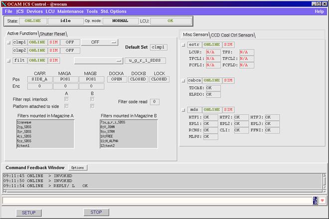
Figure 3 ICS stand-alone engineering GUI
The ICS Test Software shall consist of [ISDD35]:
- Low-level
LCU test procedure for the Lakeshore special device. It will be
implemented in file xxilak/test/xxilakTest.c
- High-level WS test procedure for the Lakeshore special device. The inscSelfTestICS utility will be used for this purpose. The procedure will be defined through the keywords INS.SENSi.TEST* in file xxmcfgTEST.cfg
- Self-test
procedure. The inscSelfTestICS
utility will be used for this purpose. The procedure will be defined
through the keywords OCS.INS1.TEST* in file xxmcfgTEST.cfg
- Alarms
test procedure. The reaction of the Software to each alarms condition is
tested. Whenever it is not possible or too risky to reproduce an alarm
condition in hardware, it is simulated in software.
All test procedures will test also the most
common or critical error cases.
ICS will
be based on icb and icbpan.
The cmm modules belonging to ICS are [ISDD34]:
- xxi. It is the main module and includes the ICS WS front-end and LCU simulator.
- xxipan. It includes the ICS stand-alone GUI
- xxilak. It includes the code for the Lakeshore special device
5 DETECTOR CONTROL SOFTWARE (DCS)
This
Chapter describes the design of the DCS package. Depending on its size, or for
any other reasons, it might be convenient to place it in a separate dedicated
document. In such case, this chapter is replaced by a simple reference to the
separate document.
In
case of non standard DCS, or special extensions of the standard functionality,
the design should be based on the UML notation.
Use
cases should describe the most important or critical operations. For each Use
Case a description of the actors involved, performance requirements, basic
course, exception course is mandatory; a Use Case Diagram is recommended.
Depending on the context, other diagrams may be used.
The instrument is equipped with two science detector cameras [ISDD15].
Two
DCSs will be in place, each controlling one of the two science cameras [ISDD16].
The DCS for the UV camera will be an instance
of the standard FIERA package [ISDD17].
The UV CCD detector size will be 2028 x 2048
pixels, upgradeable to 4096 x 4096 [ISDD18].
The DCS for the IR camera will be an
instance of the standard IRACE package [ISDD19].
The IR detector size will be 1024 x 1024
pixels [ISDD20].
Remove
this section if standard DCS packages are used
Remove
this section if standard DCS packages are used
Remove
this section if standard DCS packages are used
Remove
this section if standard DCS packages are used
Remove
this section if standard DCS packages are used
If
standard DCS packages are used, the interface is also automatically defined by
those packages. Nevertheless for clarity it might be better to remind it.
The programmatic interface consists of:
- Interface to the OS Server. It consists of:
- Command Definition Table for the DCS Server process (see 11.2.1)
Provide
the CDT if different from the standard one
- Setup keywords (see 11.2.2)
Provide
the list of keywords in addition or alternative to the standard ones
- On-line database attributes (see 11.2.3)
Provide
the list of attributes in addition or alternative to the standard ones
- FITS files containing the detector data and the DET header keywords (see 11.2.4)
Provide an example of FITS header if different from the standard one
The Graphical User Interface consists of:
- DCS engineering GUI
Present a mockup if different from the
standard one
- Real-Time Display GUI: based on rtdb for the UV camera and irtd for the IR camera [ISDD52]
Present
a mockup if different from the standard one
The following read-out modes are foreseen (if defined in another document, juts refer to that document) [ISDD60]:
- UV CCD:
1.
two outputs, 125
kHz clock rate, no binning, max. one window
2.
one output, 250
kHz clock rate, binning 2x2, no window
3. ……
- IR detector:
1.
one output, 500
kHz clock rate, max. one window
2.
…..
Considering the chip size, the fastest acquisition will therefore be xx sec for the UV camera and yy sec for the IR camera.
No real-time or in general “fast” data
processing (such that it must be performed on the DCS LCU) is requested.
The maximum size of a FITS file containing
data from the UV camera is 34 MB
The maximum size of a FITS file containing data from the IR camera is 2.2 MB
The maximum number of keywords in the FITS
header is 1000, corresponding to 30 FITS records. The standard provisions available
in FIERA (OLDB attribute images:transfer.itHeaderSize)
and IRACE (configuration keyword DET.FITSHDR.SIZE.NO) will be used to make sure
that DCS reserves enough space for the header (this point is important, otherwise the merging of the FITS information
form the various sub-systems, done by OS, may take extremely long, thus drastically
reducing observing efficiency)
See 5.2
The DCS configuration for each camera is stored in dedicated cmm modules (see 5.7) and consists of:
- One file containing configuration parameter values. Give name and contents
- Clock pattern files and directories. Give name and contents
The DCS configuration for the UV camera is installed during the INSTALL_CCD phase of pkginBuild.
The
DCS configuration for the IR camera is installed during the INSTALL_CCD phase
of pkginBuild
The DCS Test Software shall consist of [ISDD67]:
- Self-test procedure for the UV camera, consisting of taking one exposure for each read-out mode. The inscSelfTestDCS utility will be used for this purpose. The procedure will be defined through the keywords OCS.DET1.TEST* in file xxmcfgTEST.cfg
- Self-test
procedure for the IR camera, consisting of taking one exposure for each
read-out mode. The inscSelfTestDCS
utility will be used for this purpose. The procedure will be defined
through the keywords OCS.DET2.TEST* in file xxmcfgTEST.cfg
All test procedures will test also the most
common or critical error cases.
DCS for the UV camera is based on the FIERA package.
DCS for the IR camera is based on the IRACE package.
Image display is based on the rtd
package.
The cmm modules belonging to DCS are [ISDD65]:
- xxdir. It includes the configuration files for the IR camera.
- fcdXXXX. It includes the configuration files for the UV camera. It is delivered by ESO.
This
Chapter describes the design of the OS package. Depending on its size, or for
any other reasons, it might be convenient to place it in a separate dedicated
document. In such case, this chapter is replaced by a simple reference to the
separate document.
The Observation Software (OS) is the highest layer of the control Software and will run in the Instrument Workstation (see Figure 2).
The
design should be based on the UML notation.
If
special processes are implemented, a UML component diagram may be useful to
describe their relationship with the standard processes.
Figure 4 shows the Component Diagram for OS (example taken from Omegacam OS design document)
OS consists of:
- OS Server process xxoControl, responsible for the execution of single exposures.
- OS Archiver process bossArchiver_xxo, responsible for archiving the results of exposures in FITS files.
- If applicable, any process dedicated to
special features
- If applicable, Supervisory OS
- Templates, defining and running sequence of exposures
- OS Control and Status panels
The
OS processes (Server, Archiver and, if applicable, SOS) will be based on the
standard package boss. [ISDD47]
Templates
will be based on the standard package tpl.
The following sections will concentrate only on the features, such as special classes, which are not included in the standard common Software.
Figure 4 OS component diagram
In
case of one SOS coordinating several
Do not
repeat here the functionality and classes already provided by boss. Concentrate
instead on the special features and classes needed and to be implemented on
top. Use the UML notation and related diagrams.
Describe
here the special classes which have to be implemented and their purpose.
The following special classes will be developed for the OS Server process xxoControl, based on boss:
- xxoINTERFACE_SV. This is a subclass of bossINTERFACE dedicated to the interface to the slit viewer special process (see 6.2.3).
- ….
The relationship between classes is described in the Class Diagram shown in Figure 5 (example taken from Omegacam OS design document)
All the above classes will use the standard tool ctoo to access the value of configuration keywords.
Figure 5 OS Server class diagram
The following instrument modes (keyword INS.MODE) are foreseen for this OS: [ISDD59]
- UVSPEC (UV spectroscopy)
- IRSPEC (IR spectroscopy)
- DSPEC (Dichroic spectroscopy)
- IRIMG (IR Imaging)
See 11.3.3 for more details
The following sub-set of the standard
exposure types (keyword DPR TYPE), defined in [AD 10], will be used [ISDD68]:
- OBJECT
- SKY
- STD
- FLUX
- SPECTEMPL
- BIAS
- DARK
- FLAT
- LAMP
- WAVE
- FMTCHK
- ORDERDEF
The programmatic interface consists of:
- Interface to TCS using the standard tif commands and library
The Graphical User Interface, based on the VLT panel editor, consists of:
- OS Control GUI, shown in Figure 6 (example taken from FLAMES) [ISDD70]
- OS Status GUI, shown in Figure 7 (example
taken from GIRAFFE) [ISDD71]
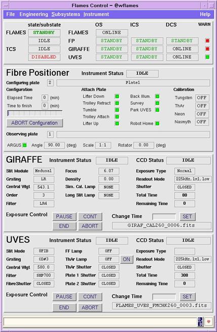
Figure 6 OS Control GUI
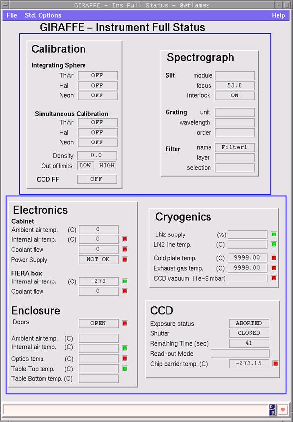
Figure 7 OS Status GUI
The following Use Cases describe the most common/critical circumstances where this process is involved:
- Perform Exposure
Description: ….
Actors: ….
Performance: ….
Frequency: ….
Preconditions: ….
Basic Course:
· ….
· ….
Exception Course: ….
· ….
Diagrams: Sequence Diagram (see Figure 8, example taken from Omegacam OS design document).
Figure 8 Perform Exposure Sequence Diagram
- …..
Do not
repeat here the functionality and classes already provided by boss. Concentrate
instead on the special features and classes needed and to be implemented on
top. Use the UML notation and related diagrams.
The following special classes will be developed for the OS Archiver process bossArchiver_xxo, based on boss:
- xxoARCHIVER. This is a subclass of bossARCHIVER.
- ….
The relationship between classes is described in the Class Diagram shown in Figure 9 (example taken from Omegacam OS design document)
Figure 9 OS Archiver class diagram
The following Use Cases describe the most common/critical circumstances where the classes above are used:
- …….
Description: ….
Actors: ….
Performance: ….
Frequency: ….
Preconditions: ….
Basic Course:
· ….
· ….
Exception Course: ….
· ….
Diagrams: ….
- …..
This
is an example of OS special process, not necessarily within the scope of every
instrument.
Describe
here the purpose of the special process, why you intend to dedicate an entire
process to the described functionality, and not, for example, one dedicated
class within the OS Server process.
The
design should be based on the UML notation.
Use
cases should describe the most important or critical operations. For each Use
Case a description of the actors involved, performance requirements, basic
course, exception course is mandatory; a Use Case Diagram is recommended.
Depending on the context, other diagrams may be used. Typically Class Diagrams,
State Chart Diagrams and Sequence Diagrams should be used in the design of OS
special processes.
The slit viewer server xxoSvControl takes care of all actions related to the slit viewer TCCD camera. They consist of:
- Start loop of exposures on the slit viewer camera and display images
- Center object in the slit by offsetting the telescope
- Start loop of exposures on the slit viewer camera
- …..
The process will be based on the standard evh functionality.
The following classes will be implemented:
- ….
The relationship between classes is shown in the Class Diagram in Figure TBD.
The programmatic interface consists of:
- Interface to the OS Server. It consists of:
- Command Definition Table for the xxoSvControl Server process (see 11.3.2)
Provide
the CDT
- On-line database attributes
Provide
the list of attributes
- Interface to the slit viewer DCS Server. It consists of:
- Command Definition Table for the DCS Server process
Provide
the CDT if different from the standard one
- On-line database attributes
Provide
the list of attributes in addition or alternative to the standard ones
- FITS
files containing the slit viewer image data
- Interface to the OS Archiver. It consists of:
- FITS files containing the slit viewer image data. All these files will be regularly archived.
The Graphical User Interface consists of:
- Slit viewer engineering GUI (see Figure TBD)
Present
a mockup, produced with the VLT panel editor
- Real-Time
Display GUI
Present
a mockup, based on rtdb
Table
3 shows the list of keywords foreseen for this process at
runtime and described in the dictionary XXXX_OS.
Table 3 OS Setup and Status keywords
|
NAME |
Type |
Description |
|
OCS.GS.ALPHA |
Setup/Header |
RA of Guide Star |
|
OCS.GS.DELTA |
Setup/Header |
DEC of Guide Star |
|
….. |
|
|
The states and related transitions are described in the State Chart Diagram shown in Figure TBD.
The following Use Cases describe the most common/critical circumstances where the slit viewer server is involved:
- Center object in the slit
Description: Before starting science observation, the object must be centered on the slit. A loop of exposures on the slit viewer TCCD camera is started and the lit viewer server process is requested to determine the centroid of the object and send an offset to the telescope to bring the object to the slit center.
Actors: OS Server, Slit Viewer DCS, TCS
Performance: corrections accuracy of 1 arcsec
Frequency: N/A
Configuration: N/A
Commands: SETUP
Preconditions: The Instrument is ONLINE
Basic Course:
· OS slit viewer server xxoSvControl receives a command SETUP –function OCS.SV.CENTER T from an acquisition template.
· ……
Exception Course: failed to send correction to TCS
· return FAILURE
Diagrams: Sequence Diagram, see Figure TBD
- …..
Describe
only the keywords explicitly defined and needed for your instrument
Table
3 shows the list of configuration keywords foreseen for
OS and described in the dictionary XXXX_CFG.
Table 4 OS configuration keywords
|
NAME |
Description |
|
OCS.AG.PROCNAME |
Name of the secondary guiding special
process |
|
OCS.AG.LCUENV |
Name of the LCU environment where the
instrument secondary AG sw runs |
|
….. |
|
All keywords used by OS at runtime are registered in the dictionary XXXX_OS.
All dictionaries are contained in module dicXXXX.
The implementation of templates will be based on the rules defined in [RD 08] and on the standard tool tpl [ISDD56].
The
parameter values used within OS templates will always be in user units and
never in engineering units (e.g. encoder units) [ISDD72]
If the
detailed design of templates is already described in another document (e.g.
Calibration Plan or Templates Manual), then just refer to that document.
The
sequence foreseen for each template could be described also with the help of a
UML Sequence Diagram.
The templates currently foreseen are: [ISDD57]
·
Acquisition
1. XXXX_UVSPEC_acq. UV Spectroscopy standard object acquisition
Parameters:
· Instrument mode (INS.MODE)
· Object RA (TEL.TARG.ALPHA)
· Object DEC (TEL.TARG.DELTA)
· ….
Setup Reference file: xxoseq/config/XXXX_UVSPEC.ref
Sequence:
a. Set instrument mode
b. Preset telescope
c. Wait of auto-guiding and active optics active
d.
……
2.
….
·
Calibration
- XXXX_UVSPEC_cal_std. UV Spectroscopy standard calibration. The first operation will be a SETUP command to turn on the calibration lamp selected (to optimize exposure cycle due to lamp warm-up time) [ISDD54]
Parameters:
· Instrument Mode (INS.MODE)
· Lamp name (INS.LAMP)
· Integration time (DET1.WIN1.UIT1)
· ……
Setup Reference file: xxoseq/config/XXXX_UVSPEC.ref
Sequence:
a. Set instrument mode
b. Switch lamp on
c. Wait for lamp to warm-up
d. Take a full frame exposure (integration time xx sec)
- ….
·
Science
- XXXX_UVSPEC_obs_std. UV Spectroscopy standard observation. Before starting the exposure, the derotator continuous motion must be started, with SETUP –function INS.DROT.MODE SKY [ISDD55]
Parameters:
· Instrument mode (INS.MODE)
· Integration time (DET1.WIN1.UIT1)
·
…..
Setup Reference file: xxoseq/config/XXXX_UVSPEC.ref
Sequence:
a. Set instrument mode
b. Setup the instrument according to the given parameters value
c. Take a full frame exposure (integration time specified by the user)
- ….
The following classes will be implemented:
- xxoseqOBS, subclass of tplOBS. Methods: [ISDD69]
- Preset
- …..
OS shall provide to P2PP, as part of the xxotsf module, the Instrument Package XXXX.zip, consisting of all the OS templates and
the Instrument Summary File default.isf.
The OS Test Software shall consist of [ISDD75]:
- OS processes test (including SOS, if applicable). Execute a sequence of typical exposures. The inscSelfTestOS utility will be used for this purpose. The procedure will be defined through the keywords OCS.OS.TEST* in file xxmcfgTEST.cfg
- OS
templates test. Execute the self-test OBD XXXX_gen_tec_SelfTest.obd consisting of the whole list of
implemented templates. The inscSelfTestTPL
utility will be used for this purpose. The procedure will be defined
through the keywords OCS.TPL.TEST* in file xxmcfgTEST.cfg
All test procedures will test also the most common or critical error cases.
The OS Server and Archiver processes are based on the standard package boss (see [RD 10]), which is conform to the VCS-Archive interface requirements (see [AD 08])
Templates are based on the standard package tpl (see [RD 08]) and are executed through the standard bob utility (see [RD 11]), which is conform to the VCS-OH interface requirements
(see [AD 07]).
The OS GUIs are built using the CCS panel
editor utility.
The cmm modules belonging to OS are [ISDD74]:
- xxo. It is the main module and includes the OS processes code.
- xxopan. It includes the code for the OS GUIs
- xxoseq. It includes the templates code and the templates test obd files
- xxotsf.
It includes the templates signature files and instrument package.
This
Chapter describes the design of the MS package. Depending on its size, or for
any other reasons, it might be convenient to place it in a separate dedicated
document. In such case, this chapter is replaced by a simple reference to the
separate document.
Besides the scientific operation at the
telescope, the control software needs to support the testing activities in
All maintenance operations supported by
Software will be implemented as technical Templates, as requested in [AD 02], and are listed in section 7.1
The
whole Instrument Configuration will be contained in configuration files within
the module xxmcfg. [ISDD32]
Only
user xxxxmgr will be allowed to
change the contents of configuration files and thus to change the instrument
configuration. User xxxx can only
read the contents of the configuration files [ISDD81].
The
standard mechanism, described in [RD 12], to change and save the instrument configuration will
be used [ISDD82].
The implementation of templates will be based on the rules defined in [RD 08] and on the standard tool tpl.
The parameter values used within MS templates will be in user units, whenever possible, or engineering units, if necessary [ISDD76]
The
sequence foreseen for each template could be described also with the help of a
UML Sequence Diagram.
The following templates are foreseen [ISDD58]:
- XXXX_IRIMG_cal_focus. Instrument
focus. Measure the instrument focus. It
will use a MIDAS procedure[2] to for the on-line image processing [ISDD53].
Parameters:
· Steps size (INS.FOCUSSTEP)
· …..
Setup Reference file: xxoseq/config/XXXX_IRIMG.ref
Sequence:
a. Set instrument mode
b. Take 7 full frame exposures 1 sec each by moving device xyz stepwise by xx mm
c. Determine the optimal focus position and log its value in FITS format [ISDD79]
- XXXX_gen_tec_filtXchg. Filter exchange. It helps maintenance staff to exchange a filter, log this operation and save the new Instrument Configuration.
Parameters:
· Old filter ID (INS.FILT1.OLDID)
· New filter ID (INS.FILT1.NEWID)
· …..
Setup Reference file: N/A
Sequence:
a. ……..
b. Ask the operator to validate this change in the instrument configuration [ISDD80]
c. Log the change in FITS format
- XXXX_gen_tec_ln2refill. LN2 tank refilling. It helps maintenance staff to refill the LN2 tank and to verify the new tank level
Parameters:
· ……
Setup Reference file: N/A
Sequence:
a. ……..
- XXXX_gen_tec_motcurr. Motor current. Run a motor at full speed, measure the current and record the data for trend analysis.
Parameters:
· Motor name (INS.MOTNAME)
· Speed (INS.SPEED)
· Sampling period (INS.PERIOD)
· …..
Sequence:
a. ……..
7.2.1 Instrument technical package
MS shall provide to P2PP the Instrument Technical Package XXXX_tec.zip [ISDD61], consisting of all the MS templates and the Instrument Summary File technical.isf.
The MS Test Software shall consist of [ISDD77]:
- MS
templates test. Execute a self-test OBD consisting of the whole list of implemented
technical templates (see [RD 04]). The inscSelfTestMS
utility will be used for this purpose. The procedure will be defined
through the keywords OCS.MS.TEST* in file xxmcfgTEST.cfg
All test procedures will test also the most
common or critical error cases.
Templates are based on the standard package tpl (see [RD 08]) and are executed through the standard bob utility (see [RD 11]).
The cmm modules belonging to MS are [ISDD78]:
- xxmcfg. It includes all instrument configuration files
- xxmseq. It includes the technical templates code and the templates test obd files
- xxmtsf.
It includes the technical templates signature files and the technical
instrument package.
8
OBSERVER SUPPORT SOFTWARE (
This Chapter describes the design of the
The standard P2PP utility is used to prepare Observation Blocks [ISDD73]
No cmm module is foreseen for
The Software
installation procedure will be based on the standard tool pkgin and the related files will be part of the installation module
xxins [ISDD86].
Being the development distributed (see [RD 13]), one additional installation module for each location will be dedicated to the hw configuration and targets defined for that location:
- xxmgar for TARGET CM_FULL and CM_WS at Garching
- xxmAAA for TARGET DEV_AAA and INTEGRATION at Observatory AAA
- xxmBBB for TARGET DEV_BBB at Observatory BBB
- xxmCCC
for TARGET DEV_CCC at Observatory CCC
Scripts xxinsStart
and xxinsStartup will be implemented to
startup the whole instrumentation
software or parts of it. Script xxinsStop
will be implemented to shutdown the whole instrumentation software or
parts of it.
These scripts will be based
on standard features available in the module stoo [ISDD08].
All critical performance requirements must be analyzed here. In
particular, it shall be investigated if the usage of standards fulfills all
performance requirements or special solutions must be considered instead.
Information about performance aspects related to the usage of the VLT common
software is available in the VLT software documentation (User Manuals) or may
be provided by ESO software staff. Whenever uncertainties are present,
dedicated prototyping is mandatory and the results must be presented here,
together with the conclusions and the proposed solutions.
The following sub-sections are just examples of typical fields where performance
requirements are specified. They should not be considered exhaustive for all
instruments nor are all of them necessarily applicable to all instruments.
9.3.1 Initialization and setup
It is required that the initialization and setup of the whole instrument does not exceed xx sec. Because all devices will be initialized in parallel (see 4.1.4), the overall initialization or setup time for the whole instrument shall correspond to that device, which takes longer. The devices which require higher accuracy and will take longer time are the cross-dispersers. A prototype has been implemented, showing that the initialization and setup of the cross-dispersers takes less than the required maximum time. [ISDD12]
It is required that
the fastest acquisition for a 4096x4096 detector does not exceed xx sec with a
maximum overhead for the image transfer to the IWS of xx sec. This corresponds
to yy Mbit/sec data rate. Such a
rate can be sustained by the Gigabit Ethernet
network connection between detector LCU and Instrument Workstation and by
the hard disk model and related interface mounted on VLT standard IWS [ISDD10].
For the foreseen
on-line data processing on the IWS, the standard tool used guarantees a
satisfactory response time.
It is required that the maximum delay between end of image acquisition and end of image display does not exceed xx sec
Using the Template
Instrument as test bench and the VLT standard real-time display tool, we have
determined a maximum delay over 20 acquisitions
of yy sec. This shows that the VLT standard packages (FIERA and IRACE for
DCS and rtd for the Real Time
Display) are good enough for our requirements [ISDD11].
If the two DCSs have to be synchronized between each other or with the
ICS LCU or with some machine, a solution has to be presented, in form of UML
use case(s) should be used, possibly together with a Sequence Diagram. If the
solution is distributed among different platforms, a Deployment Diagram should
be added. If the solution foresees dedicated processes, a Component Diagram is
recommended.
The results of prototyping, showing that the proposed solution fulfills
the requirements in terms of accuracy and latency, should also be presented
here.
It is required that the execution of a bias full frame, from the start till when the complete FITS file is available on the IWS for being archived, shall not exceed xx sec (see [AD 11]).
Using the Template
Instrument as test bench, we have determined a maximum execution time over 20 exposures with the FIERA DCS of yy sec
and with the IRACE DCS of zz sec. This shows that the VLT standard packages
(FIERA and IRACE for DCS and boss for OS) are good enough for our requirements [ISDD09].
The standard user
station for an instrument is described in [AD 02] and consists of two screens. If more screens are
needed, it must be indicated here as explicit requirement.
The User Station shall consist of [ISDD43]:
- Screen 1:
- Workspace 1: BOB GUI and OS Control GUI.
- Workspace 2: OS status GUI
- Workspace 3: ICS stand-alone GUI
- Workspace 4: Detector stand-alone GUI
- Screen 2: Detector Real-Time Display GUI, Alarms GUI (VLT standard) [ISDD42] and Logs GUI (VLT standard)
Optionally, sounds will be associated to the following alarms:
- …..
GUIs will always be
started/stopped as the result of the execution of the script xxinsStart/xxinsStop. They will
never be started or stopped automatically by processes. The only exception is
represented by small acknowledgement panels, which may be started from
templates [ISDD85].
The editing and selection of Observation Blocks to be executed shall be done on the console screen of the Observation Handling (P2PP) Workstation [ISDD44].
A separate screen will be available for off-line data reduction [ISDD45].
The foreseen alarms are described in 4.3.5.
Software Configuration Control shall be guaranteed by using
official releases of the VLT Software and the standard cmm facilities to
archive and modify instrument specific code [ISDD49].
It will be possible
to build and install from scratch the whole instrument software. The
procedure to achieve this will be based
on the standard tool pkginBuild [ISDD05].
Instrument specific
code will be developed according to the rules defined in [AD 05] [ISDD50]
The documentation to be produced for the Control Software is defined in [AD 02].
Each Software document
is archived in a separate cmm module (same name as the
document number). The format of the
source file is WinWord [ISDD63].
9.9 Adaptability and enhancement potential
Being the Software heavily based on VLT Software standard components, thus minimizing the amount of specific code to be developed, it will be able to run on any platform supported by the VLT Common Software.
No enhancements to the baseline are at the present stage
foreseen.
Being the Software heavily based on VLT Software standard
components, no specific training for users (scientists, operators and engineers)
with experience of VLT operations is foreseen. Paranal staff is however supposed
to be involved in the PAE in
10 DEVELOPMENT AND TEST FACTORS
See [RD 13]
The set of tests described in [RD 04] and [AD 11], and in the present document at sections 4.5, 5.5, 6.7 and 7.3, are part of the Instrumentation Software package deliverables.
They will be developed in parallel with the control code and
will periodically (at least once every two months) repeated as part of the
exercise aiming to rebuild the Control Software from scratch, thus aligning the
running version at all development and integration locations. For this reason, the
test procedures will be automatic
and the results reproducible, also in absence of some hardware components (i.e.
with devices in simulation); the VLT
standard tool tat will be used for
this purpose [ISDD91]
It will also be the basis for the PAE run.
11.1.1 Lakeshore special device server
Add manual page of the
xxilakServer process
11.1.2 Lakeshore special device monitoring task
Add manual page of the
xxilakMonitor process
11.1.3 Lakeshore special device operational logs
Add here
an extract of the operational logs produced by the special device (short-FITS
format)
Add manual page of the xxiControl process
and its CDT, if different from the default one defined by icb.
The CDT of the xxiControl process is identical to that
defined by icb (see ic0Control.cdt)
Add manual page of the ICS WS special
classes.
Add here an extract of
the part of the configuration file xxmcfgINS.cfg which defines the assemblies
INS.ASSEMBLY1 "INS.LAMP"
INS.ASSEMBLY1.HEADER T
INS.ASSEMBLY1.KEY1 "OFF"
INS.ASSEMBLY1.VAL1 "INS.LAMP1.ST F INS.LAMP2.ST F INS.LAMP3.ST F INS.LAMP4.ST F INS.SHUT1.ST F"
INS.ASSEMBLY7.KEY2 "TAL1"
INS.ASSEMBLY1.VAL2 "INS.LAMP1.ST T INS.LAMP2.ST F INS.LAMP3.ST F INS.LAMP4.ST F INS.SHUT1.ST T"
INS.ASSEMBLY7.KEY3 "TAL2"
INS.ASSEMBLY1.VAL3 "INS.LAMP1.ST F INS.LAMP2.ST T INS.LAMP3.ST F INS.LAMP4.ST F INS.SHUT1.ST T"
INS.ASSEMBLY7.KEY4 "FFL1"
INS.ASSEMBLY1.VAL4 "INS.LAMP1.ST F INS.LAMP2.ST F INS.LAMP3.ST T INS.LAMP4.ST F INS.SHUT1.ST F"
INS.ASSEMBLY7.KEY5 "FFL2"
INS.ASSEMBLY1.VAL5 "INS.LAMP1.ST F INS.LAMP2.ST F INS.LAMP3.ST F INS.LAMP4.ST T INS.SHUT1.ST F"
Add here an extract of
the part of the OLDB definition files where alarms are defined.
Alarms are defined in file xxiINS_LAKE.class:
#ifndef
MAKE_VXWORKS
ATTRIBUTE
double tempMax // maximum camera
temperature
ATTRIBUTE
int32 alarm0 // alarm flag for blue temperature
BEGIN
Definition
IF([.state] < lccdevSTD_STATE_STANDBY, 0, IF([.last(0)] =
ic0senVALUE_ILLEGAL, 0, IF([.last(0)] > [.tempMax], 1, 0)))
END
alrmAnalog2stHelp("alarm", alarm0,
#endif
Add here an example of
the file produced by ICS as result of the command STATUS –header –dumpFits
Show here the contents
of the dictionary file XXXX_CFG.
Present here the
manual page and CDT of the DCS server process, if different from the standard
one
Present here a list of
keywords other than the standard ones
Present here a list of
OLDB attributes other than the standard ones
Add here an example of
the file produced by DCS and containing the DET keywords for the header, if
different from the standard one.
11.3.1 OS Server special classes
Add manual page of the
OS Server special classes.
11.3.2 OS Secondary Guiding Server
Add CDT of the process
and the manual page of the process.
The following is an extract of file xxmcfgINS.cfg, where the modes and the related setup are defined:
#
# 5.5 Instrument modes
#
OCS.MODE1.NAME "UVSPEC";
OCS.MODE1.SETUP "-function INS.MIRR2.NAME UV";
OCS.MODE1.SUBSYST "UVDCS ICS UT1";
OCS.MODE1.PATH "UV";
OCS.MODE2.NAME "IRSPEC";
OCS.MODE2.SETUP "-function INS.MIRR2.NAME IR";
OCS.MODE2.SUBSYST "IRDCS ICS UT1";
OCS.MODE2.PATH "IR";
OCS.MODE3.NAME "DSPEC";
OCS.MODE3.SETUP "-function INS.MIRR2.NAME
DICHROIC";
OCS.MODE3.SUBSYST "IRDCS UVDCS ICS UT1";
OCS.MODE3.PATH "DICHROIC";
OCS.MODE4.NAME "IRIMG";
OCS.MODE4.SETUP "-function INS.MIRR2.NAME IR
INS.GRAT2.NAME FREE";
OCS.MODE4.SUBSYST "IRDCS ICS UT1";
OCS.MODE4.PATH "IR";
11.5
The following table aims to set a link between the
functional specifications defined in [AD 12] and the contents of this document.
|
Func. Spec |
DOC. |
LABEL |
DESCRIPTION |
|
ISFS01 |
[AD 12] |
ISDD01 on page 12 |
Define Instrument ID and prefix in agreement with ESO |
|
ISFS02 |
[AD 12] |
ISDD02 on page 12 |
Define LCUs with TIM board |
|
ISFS03 |
[AD 12] |
ISDD03 on page 12 |
Define Instrument LAN nodes and names |
|
ISFS04 |
[AD 12] |
ISDD04 on page 13 |
Instrument Software divided into the standard INS Modules |
|
ISFS05 ISFS08 |
[AD 12] |
ISDD05 on page 39 |
Use pkginBuild to build and install from scratch the Software |
|
ISFS06 |
[AD 12] |
ISDD06 on page 14 |
Define names of CCS environments, following standard naming conventions |
|
ISFS07 |
[AD 12] |
ISDD07 on page 14 |
Define name of the installation user (manager) and run-time user |
|
ISFS09 ISFS10 |
[AD 12] |
ISDD08 on page 38 |
Scripts to startup and shutdown the Software or part of it are based on stoo |
|
ISFS11 |
[AD 12] |
ISDD09 on page 39 |
DCS can cope with the highest required duty cycle |
|
ISFS12 |
[AD 12] |
ISDD10 on page 38 |
Define network and disk config. to support data acquisition requirements |
|
ISFS13 |
[AD 12] |
ISDD11 on page 38 |
rtd can cope with maximum accepted delay between acquisition and display |
|
ISFS14 ISFS15 |
[AD 12] |
ISDD12 on page 38 |
Prototype shows that ICS can fulfill the required init and setup time |
|
ISFS16 |
[AD 12] |
ISDD13 on page 16 |
Define number of ICSs |
|
ISFS17 |
[AD 12] |
ISDD14 on page 16 |
List of ICS devices |
|
ISFS18 |
[AD 12] |
ISDD15 on page 24 |
Define number of cameras |
|
ISFS19 |
[AD 12] |
ISDD16 on page 24 |
Define number of DCSs |
|
ISFS20 |
[AD 12] |
ISDD17 on page 24 |
UV DCS uses the standard FIERA package |
|
ISFS21 |
[AD 12] |
ISDD18 on page 24 |
UV detector size |
|
ISFS22 |
[AD 12] |
ISDD20 on page 24 |
IR detector size |
|
ISFS23 |
[AD 12] |
ISDD21 on page 17 |
Define derotator modes |
|
ISFS24 |
[AD 12] |
ISDD22 on page 16 |
Lamps in stand-by state |
|
ISFS25 |
[AD 12] |
ISDD23 on page 18 |
Measures foreseen to overcome mechanical backlash |
|
ISFS26 |
[AD 12] |
ISDD24 on page 17 |
Gratings setup parameters |
|
ISFS27 |
[AD 12] |
ISDD25 on page 17 |
Sensors sampling period |
|
ISFS28 |
[AD 12] |
ISDD26 on page 18 |
Define list of cryogenic devices |
|
ISFS29 |
[AD 12] |
ISDD27 on page 18 |
Define list of ICS special devices |
|
ISFS30 |
[AD 12] |
ISDD28 on page 16 |
Use icb for ICS processes and icbpan
for ICS GUIs |
|
ISFS31 ISFS32 ISFS33 ISFS34 |
[AD 12] |
ISDD29 on page 18 |
Description of ICS states |
|
ISFS35 |
[AD 12] |
ISDD30 on page 19 |
Define list of ICS commands |
|
ISFS36 |
[AD 12] |
ISDD31 on page 21 |
Define list of Software alarms |
|
ISFS37 |
[AD 12] |
ISDD32 on page 35 |
Define cmm module containing
configuration files |
|
ISFS38 |
[AD 12] |
ISDD28 on page 16 |
ICS param. values shall not be changed until a new command requests for it |
|
ISFS39 |
[AD 12] |
ISDD28 on page 16 |
Status of ICS on-going and completed actions shall be
accessible |
|
ISFS40 |
[AD 12] |
ISDD28 on page 16 |
Check for ICS parameters value validity |
|
ISFS41 |
[AD 12] |
ISDD28 on page 16 |
ICS keywords are syntactically checked against dictionary |
|
ISFS42 |
[AD 12] |
ISDD33 on page 19 |
Define list of ICS OLDB attributes to be scanned and scanning mode |
|
ISFS43 |
[AD 12] |
ISDD34 on page 22 |
Define list of ICS cmm
modules, following the naming conventions |
|
ISFS44 |
[AD 12] |
ISDD35 on page 22 |
Define list of scripts/procedures to test ICS |
|
ISFS45 |
[AD 12] |
ISDD36 on page 21 |
Define list of ICS assemblies |
|
ISFS46 |
[AD 12] |
ISDD37 on page 19 |
Define ICS hardware simulation levels |
|
ISFS47 |
[AD 12] |
ISDD38 on page 19 |
ICS hardware simulation is not hidden to the user |
|
ISFS48 |
[AD 12] |
ISDD39 on page 21 |
ICS and DCS GUIs are foreseen and based on the VLT panel editor |
|
ISFS49 |
[AD 12] |
ISDD40 on page 20 |
Define list of ICS and DCS actions, events, values to be logged |
|
ISFS50 |
[AD 12] |
ISDD41 on page 21 |
Define contents of the FITS header |
|
ISFS51 |
[AD 12] |
ISDD42 on page 39 |
Alarms permanently displayed in the User Station with standard tool |
|
ISFS52 |
[AD 12] |
ISDD40 on page 20 |
Alarms monitoring also in STANDBY state |
|
ISFS53 |
[AD 12] |
ISDD42 on page 39 |
Alarms are logged |
|
ISFS54 |
[AD 12] |
ISDD42 on page 39 |
Define sounds associated to alarms |
|
ISFS55 |
[AD 12] |
ISDD43 on page 39 |
Define User Station screens contents |
|
ISFS56 |
[AD 12] |
ISDD44 on page 39 |
Define screen for P2PP |
|
ISFS57 |
[AD 12] |
ISDD45 on page 39 |
Define WS for Off-line data reduction |
|
ISFS58 |
[AD 12] |
ISDD46 on page 12 |
Define number of disks and their size and speed to cope with requirements |
|
ISFS59 |
[AD 12] |
ISDD47 on page 26 |
Archive all image files in FITS format conform to ESO standards |
|
ISFS60 |
[AD 12] |
ISDD47 on page 26 |
Archive in background |
|
ISFS61 |
[AD 12] |
ISDD48 on page 18 |
Parallel setup of devices |
|
ISFS62 |
[AD 12] |
ISDD49 on page 39 |
Use cmm for Software configuration
control management |
|
ISFS63 |
[AD 12] |
ISDD50 on page 39 |
VLT programming standards applicable to Instrumentation Software |
|
ISFS64 |
[AD 12] |
ISDD51 on page 20 |
Use ctoo for configuration keywords
handling |
|
ISFS65 |
[AD 12] |
ISDD52 on page 24 |
Use rtd for Real-Time display |
|
ISFS66 |
[AD 12] |
ISDD40 on page 20 |
ICS LCU status stored in the database |
|
ISFS67 |
[AD 12] |
ISDD52 on page 24 |
Display all images |
|
ISFS68 |
[AD 12] |
ISDD53 on page 35 |
On-line data process on the IWS within templates and with standard ESO tool |
|
ISFS69 |
[AD 12] |
ISDD54 on page 33 |
Lamps with warm-up time switched on at the first setup |
|
ISFS70 |
[AD 12] |
ISDD55 on page 34 |
Continuous derotator motion during integrations |
|
ISFS71 |
[AD 12] |
ISDD56 on page 33 |
Use tpl for templates |
|
ISFS72 |
[AD 12] |
ISDD57 on page 33 |
List of acquisition, calibration and science templates |
|
ISFS73 |
[AD 12] |
ISDD58 on page 35 |
List of technical templates |
|
ISFS74 |
[AD 12] |
ISDD59 on page 27 |
List of instrument modes and related automatic settings |
|
ISFS75 |
[AD 12] |
ISDD47 on page 26 |
Use boss for OS processes |
|
ISFS76 |
[AD 12] |
ISDD60 on page 25 |
Windowed and binned readout supported |
|
ISFS77 |
[AD 12] |
ISDD61 on page 36 |
Technical Instrument Package exists |
|
ISFS78 |
[AD 12] |
ISDD62 on page 18 |
Hardware interlocks |
|
ISFS79 |
[AD 12] |
ISDD63 on page 39 |
Documentation in same electronic format used at ESO |
|
ISFS80 |
[AD 12] |
ISDD64 on page 13 |
Software architecture follows the scheme described in the INS Software Specs |
|
ISFS81 |
[AD 12] |
ISDD65 on page 25 |
DCS cmm modules follow naming
conventions |
|
ISFS82 |
[AD 12] |
ISDD66 on page 19 |
All setup and status keywords are defined in dictionaries approved by DICB |
|
ISFS83 |
[AD 12] |
ISDD32 on page 35 |
OS configuration files are in
one single cmm
module belonging to MS |
|
ISFS84 |
[AD 12] |
ISDD67 on page 25 |
List of scripts/procedures for the DCS test Software |
|
ISFS85 |
[AD 12] |
ISDD68 on page 27 |
Use standard exposure types |
|
ISFS86 |
[AD 12] |
ISDD69 on page 34 |
Functionality required from TCS. Use standard TCS-Instrument interface |
|
ISFS87 |
[AD 12] |
ISDD70 on page 28 |
Information shown in the OS control GUI, which is based on
the panel editor |
|
ISFS88 |
[AD 12] |
ISDD71 on page 28 |
Information shown in the OS status GUI, which is based on the panel editor |
|
ISFS89 |
[AD 12] |
ISDD72 on page 33 |
Parameters during science operations in high level units |
|
ISFS90 |
[AD 12] |
ISDD73 on page 37 |
Follow ICD between OS and OH |
|
ISFS91 |
[AD 12] |
ISDD74 on page 34 |
OS cmm modules follow naming
conventions |
|
ISFS92 |
[AD 12] |
ISDD75 on page 34 |
List of scripts/procedures for the OS test Software |
|
ISFS93 |
[AD 12] |
ISDD73 on page 37 |
Use standard |
|
ISFS94 |
[AD 12] |
ISDD76 on page 35 |
Parameters during maintenance operations in high level or engineering units |
|
ISFS95 |
[AD 12] |
ISDD77 on page 36 |
List of scripts/procedures for the MS test Software |
|
ISFS96 |
[AD 12] |
ISDD78 on page 36 |
MS cmm modules follow naming
conventions |
|
ISFS97 |
[AD 12] |
ISDD79 on page 35 |
Results of technical templates logged in FITS format |
|
ISFS98 |
[AD 12] |
ISDD80 on page 35 |
User acknowledgement before changing Instrument Configuration |
|
ISFS99 |
[AD 12] |
ISDD81 on page 35 |
Protection of Instrument Configuration files |
|
ISFS100 |
[AD 12] |
ISDD82 on page 35 |
Save and retrieve Instrument Configuration using standard mechanism |
|
ISFS101 |
[AD 12] |
ISDD31 on page 21 |
List of alarms |
|
ISFS102 |
[AD 12] |
ISDD83 on page 21 |
Alarms triggered only if the value of the database attribute is up-to-date |
|
ISFS103 |
[AD 12] |
ISDD84 on page 21 |
Alarm OLDB attributes for sensors follow a standard naming scheme |
|
ISFS104 |
[AD 12] |
ISDD85 on page 39 |
Panels do not pop-up and disappear automatically |
|
ISFS105 |
[AD 12] |
ISDD86 on page 38 |
Installation module follows the standard naming convention |
|
ISFS106 |
[AD 12] |
ISDD91 on page 41 |
Software test procedures
automatic and reproducible, based on tat |
|
ISFS107 |
[AD 12] |
ISDD19 on page 24 |
IRACE Software is used for Infra-red scientific cameras |
___oOo___