GRAVITY: Wavelength calibration
| |
| HC PLOTS |
| Reference wavelength |
 |
| OPD fit |
|
| Argon lamp |
|
Wavelength calibrations are measured during daytime as part of the P2VM
calibration sequence using a simulated star spectrum from the calibration unit, with one of
the grisms inserted (low, medium, or high resolution), and with the Wollaston
prism either inserted (split) or not inserted (combined polarimetry). All four
inputs are simultaneously opened.
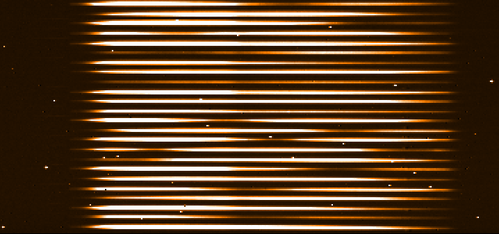 |
Wavelength calibration. Medium resolution, combined polarimetry.
|
Additional calibrations are measured weekly with the Argon lamp. These are not
used for calibrating science data but to monitor the instrument stability.
 |
Argon lamp exposure. Medium resolution, combined polarimetry.
|
 Wavelength solution
QC1_parameters
The pipeline calculates a wavelength map which matches detector pixels with
wavelengths.
| FITS key |
QC1 database: table, name |
definition |
class* |
HC_plot** |
more docu |
| QC.REFPOS1.FT1 | gravity_p2vm..refpos1_ft1 | position (pixel) of reference wavelength on detector | HC | | [docuSys coming] |
| QC.REFPOS1.FT24 | gravity_p2vm..refpos1_ft24 | position (pixel) of reference wavelength on detector | HC | | [docuSys coming] |
| QC.REFPOS1.FT48 | gravity_p2vm..refpos1_ft48 | position (pixel) of reference wavelength on detector | HC | | [docuSys coming] |
| QC.REFPOS1.SC1 | gravity_p2vm..refpos1_sc1 | position (pixel) of reference wavelength on detector | HC | | [docuSys coming] |
| QC.REFPOS1.SC24 | gravity_p2vm..refpos1_sc24 | position (pixel) of reference wavelength on detector | HC | | [docuSys coming] |
| QC.REFPOS1.SC48 | gravity_p2vm..refpos1_sc48 | position (pixel) of reference wavelength on detector | HC | | [docuSys coming] |
| QC.REFPOS2.FT1 | gravity_p2vm..refpos2_ft1 | position (pixel) of reference wavelength on detector | HC | | [docuSys coming] |
| QC.REFPOS2.FT24 | gravity_p2vm..refpos2_ft24 | position (pixel) of reference wavelength on detector | HC | | [docuSys coming] |
| QC.REFPOS2.FT48 | gravity_p2vm..refpos2_ft48 | position (pixel) of reference wavelength on detector | HC | | [docuSys coming] |
| QC.REFPOS2.SC1 | gravity_p2vm..refpos2_sc1 | position (pixel) of reference wavelength on detector | HC | | [docuSys coming] |
| QC.REFPOS2.SC24 | gravity_p2vm..refpos2_sc24 | position (pixel) of reference wavelength on detector | HC | | [docuSys coming] |
| QC.REFPOS2.SC48 | gravity_p2vm..refpos2_sc48 | position (pixel) of reference wavelength on detector | HC | | [docuSys coming] |
*Class: KPI - instrument performance; HC - instrument health; CAL - calibration quality; ENG - engineering parameter
**There might be more than one. |
Trending
The positions of two reference wavelengths (2.099 and 2.314 microns) on the
detectors are trended for the lowest spectrum on the detector.
Scoring&thresholds Wavelength solution
Scoring thresholds have been set up to median +/- 3sigma in May 2019. For the SC,
this is +/- 0.1 pixels and for the FT +/-0.04 pixels, respectively. Only reference
position 1 is scored since the other is highly correlated.
History
No particular events.
Algorithm Wavelength solution
refpos1: Position of the reference wavelength 1 (2.099 um) on the
detector in the 1st (lowest) spectrum, for FT and SC, respectively. Same for
the 24th and 48th (only for split polarimetry) spectrum.
refpos2: Position of the reference wavelength 2 (2.313 um) on the
detector in the 1st (lowest) spectrum, for FT and SC, respectively. Same for
the 24th and 48th (only for split polarimetry) spectrum.
OPD fit residuals
QC1_parameters
The pipeline calculates the RMS of the fit: * SC + b * FT + c = MET.
| FITS key |
QC1 database: table, name |
definition |
class* |
HC_plot** |
more docu |
| QC.ABCRMS.WAVEFT | gravity_p2vm..metfit_rms_ft | RMS from fit of a * SC - b * FT & c = MET | CAL |  | [docuSys coming] |
| QC.ABCRMS.WAVESC | gravity_p2vm..metfit_rms_sc | RMS from fit of a * SC - b * FT & c = MET | CAL | | [docuSys coming] |
*Class: KPI - instrument performance; HC - instrument health; CAL - calibration quality; ENG - engineering parameter
**There might be more than one. |
Trending
The RMS of the fit residuals is trended for FT and SC and for the six combinations of resolution and polarimetry mode.
Scoring&thresholds OPD fit residuals
The upper threshold for a good fit has been set to 100nm, as recommended by the consortium.
History
Introduced in August 2019.
Algorithm OPD fit residuals
Residuals of the fit between metrology, phase observed on the science camera, and phase observed on the fringe tracker:
a * SC + b * FT + c = MET. The sum of these three OPDs should be constant. If it is not the case then the fit will show high residuals.
Argon lamp
QC1_parameters
The pipeline calculates a wavelength solution from ten Argon lines on the SC
detector and compares the result from the dispersion solution to the catalogue
wavelengths.
| FITS key |
QC1 database: table, name |
definition |
class* |
HC_plot** |
more docu |
| none | gravity_wavelamp..wdiff1 | difference between actual and theoretical wavelength (in microns) | HC | | [docuSys coming] |
| none | gravity_wavelamp..disp_rms | RMS of the wavelength differences from the dispersion solution | HC | | [docuSys coming] |
*Class: KPI - instrument performance; HC - instrument health; CAL - calibration quality; ENG - engineering parameter
**There might be more than one. |
Trending
The QC1 parameters are trended for medium resolution and combined polarimetry
(which is the set-up used for weekly monitoring).
Scoring&thresholds Argon lamp
Scoring thresholds have been set up empirically and only for dispersion RMS.
History
No particular events.
Algorithm Argon lamp
wdiff1: Difference between the catalogue wavelength and the wavelength
according to the dispersion solution for Argon line 1. Same for lines 2 to
10.
disp_rms: Standard deviation of wdiff1, ..., wdiff10.
|
