1. Modeling Guidelines
1.1. Purpose and Scope
“We want to start creating models for the framework documentation (design phase). So far we do not have any dedicated MagicDraw project dedicated for the framework. We need to define what should be the strategy to follow, for instance several models per component or one big model with different parts. This ticket is requesting to define the skeleton and some modelling guidelines for keeping the framework models uniform across all framework components.”
1.2. Repository and Projects Organization
The most interesting projects related to the EELT ICS and currently archived in the Teamwork server are listed in the following table.
| Project | Description |
|---|---|
| EELT_Common_Profile | Empty but should contain the stereotypes common to INS and TCS. |
| EELT_TCS_Profile | Stereotypes and metamodel for TCS specific components. |
| EELT_INS_Profile | Stereotypes and metamodel for INS specific components. |
| EELT_CS_Parts_Catalog | Catalog of parts of ICS and TCS control systems. It includes electronics and software parts and interfaces. It should use the common stereotypes defined in EELT_Common_Profile, EELT_TCS_Profile, and EELT_INS_profile. |
| ELT_Project | Contains the EELT Project model including the observatory, TCS and the real instruments. |
| EELT_ICS_Framework | Describes the instrument framework |
| EELT_INS_Reference_Model | Describes the model of an instrument that can be used as example to build real instruments. |
| EELT_Instrument_Control_System_Conceptual_Architecture | Model used to generate the EELT ICS Architecture document. It loads the EELT_INS_Reference_Model and the EELT_CS_Parts_Catalog. |
1.3. Project Structure
It is suggested to adopt a simplified version of the structure proposed in [RD1]. Instead of creating by default all packages and leave them empty if not required, it is recommended to create only the packages needed. Packages should be organized following the system break down structure and considering different modelling aspects such as requirement analysis, behavioural analysis, structural analysis. The result is a hierarchy with two levels per subsystem as shown in Figure 1.
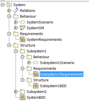
Figure 1 - Packages organization.
RECCOMANDATION: packages within a model should be organized around the system break-down structure: one package per subsystem. Each subsystem package should group the different modelling aspects in a dedicated folder [1]:
- Context [optional, only available at system level] to group the entities that represents the context of the system to be modelled.
- Data [optional] to group data types/interfaces common to subsystems belonging to the lower structural level. For example, the interfaces/data types shared by subsystem1 and subsystem2 could go in the System/Context package.
- Requirements [optional] to group requirements and requirement diagrams.
- Behaviour [optional] to group activities, state machines, sequence and related diagrams.
- Structure [mandatory] to group the break-down structure of the current subsystem.
The system break-down structure should reflect the architectural system partitioning. It may happen that this partitioning does not coincide with the Management Product Breakdown Structure. In this case, it is suggested to:
- Reproduce the PBS in a PBS View, with one package stereotyped <<ELT Product>>. The <<ELT Product>> stereotype has a tag for the PBS number and a link to the PDM folder.
- Allocate from the structure to the corresponding PDB package.
- Use a SysML Allocation Matrix to display the allocation relations (Figure 2).
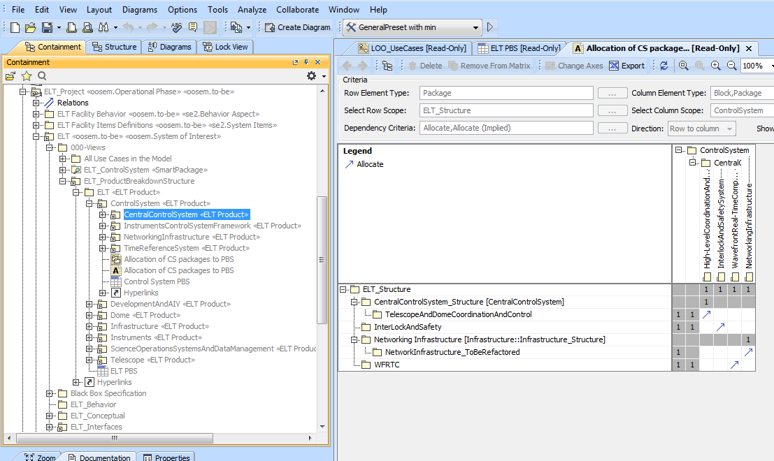
Figure – Allocation matrix between the Product Breakdown Structure and the System Breakdown Structure.
RECCOMANDATION: avoid empty packages (and delete the existing ones).
RECCOMANDATION: when creating a new project, the root package should take the name of the project.
RECCOMANDATION: use CamelCase (with upper case for the initial character) style and avoid spaces.
RECCOMANDATION: documentation of diagrams and model elements should be provided in the documentation field and displayed using notes (i.e. if possible, do not write the documentation directly in the notes).
RECCOMANDATION: a project should include a 000-Readme package diagram at the level of the root package. The diagram should provide some basic information on the project like:
- Short description of the project / model.
- The main responsible of the model.
1.4. Ontologies, OOSEM, Stereotypes and Metamodels
In the EELT projects archived in Teamwork server (for example ELT_Project) there are dependencies on profiles modules defining domain ontologies such as FoundationalOntologies, TelescopeInstrumentationOntology, UMLSysMLOntology, etc. The original idea was to define a mapping between ontologies and profiles (stereotypes and metamodels) to allow converting a SysML model into an ontology based model. Ontology based models can be used to perform some automatic reasoning. However, this effort has been put on hold due to the (very) limited amount of FTE resources allocated to modelling support. Therefore, it is suggested to avoid defining new ontologies and avoid referencing existing ontologies.
RECCOMANDATION: avoid creating new ontologies and avoid using existing ontologies since they may not be maintained in the future.
SysML is just a general-purpose modelling language and alone it does not describe the activities required to model a system. This is the reason for adopting the Object-Oriented Systems Engineering Method (OOSEM). In order to keep the model as simple as possible, the recommendation is to apply only the OOSEM activities which are strictly needed like “define logical architecture” and “allocate physical architecture”.
RECCOMANDATION: when defining and mapping the logical and physical architectures try to follow OOSEM methodology.
The EELT INS domain specific concepts are captured using stereotypes archived in EELT_INS_Profile project. TCS related stereotypes are archived in EELT_TCS_Profile while concepts which are common to both TCS and INS domains should go in EELT_Common_Profile.
RECCOMANDATION: add to EELT_INS_Profile/Stereotypes the stereotypes needed to specify EELT INS domain specific concept.
RECCOMANDATION: stereotypes should be organized by levels and comply with the following prefix convention:
- INS level includes general instrument stereotypes with prefix “ins.”, for example: <<ins.mainoptics>>.
- INS.ICS level includes stereotypes related to the control system with prefix “ins.ics.”, for example: <<ins.ics.cabinetcontrolsystem>>.
- INS.ICS.CSW level includes stereotypes related to the control software with prefix “ins.ics.csw.”, for example: <<ins.ics.csw.detectormgr>>.
- INS.ICS.CSW.DEV level includes stereotypes related to the control software devices with prefix “ins.ics.csw.dev”, for example: <<ins.ics.csw.dev.adc>>.
- INS.ICS.RTC level includes stereotypes related to the Real Time Computing facility with prefix “ins.ics.rtc.”, for example <<ins.ics.rtc.ao>>.
When adding a new stereotype, it should be clear how it can be used. This is defined in the metamodel (EELT_INS_Profile/Metamodels). The instrument metamodel represents the language describing how to build instruments. An instance of the instrument metamodel is the model of an instrument. A metamodel consists of a Block Description Diagram with one class per stereotype. The dependencies between the stereotypes show how a stereotype should be used.
RECCOMANDATION: to describe how stereotypes should be used, use a Block Description Diagram and create one Block per stereotypes with the name of the stereotype. Add the Block in the diagram and use Block relations to define the relations between stereotypes.
Unfortunately, at the moment, there is not an automatic way to create the Blocks from the stereotypes and to validate whether a model comply with the metamodel. (The only “easy” way to automatize this verification would be to write a validation rule and run it.)
RECCOMANDATION: after adding/removing/modifying a stereotype, update the metamodel.
RECCOMANDATION: when applying a stereotype to the model element, make sure that the model still complies with the metamodel.
Note that the Block Description Diagram describing the metamodel could be used as a “reference implementation” since it described all legal relations between blocks representing the stereotypes. To facilitate the usage of the metamodel as reference implementation, the Blocks in the metamodel could be stereotyped with the stereotype they represent. In this way, the instrument metamodel, for example, could be copied and the copy used as starting point for modelling a new concrete instrument. Once copied, it would be enough to rename the Blocks with concrete types.
An allocation matrix can be used to verify the mapping between blocks in metamodel and stereotype, at least to check completeness (Figure 2).
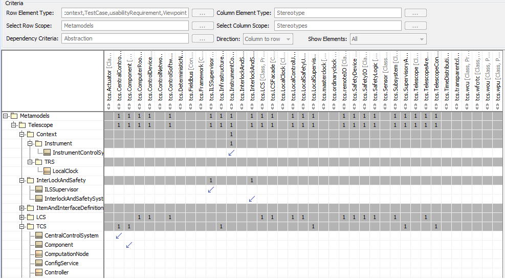
Figure – Allocation matrix between metamodel blocks and stereotypes.
1.5. Parts Catalog
The EELT_CS_Parts_Catalog project contains all the parts that can be reused to build./model an instrument or a telescope including its control software. Each part is modeled with a Block (on which the proper stereotype from EELT_INS_Profile or EELT_TCS_Profile can be applied). The parts are grouped into the following packages:
- “COTS” third party components
- “INS” instrument parts
- “ICS” Instrument Control System parts
- “CSW” Control Software parts
- “ICS” Instrument Control System parts
- “TCS” telescope parts (to be added)
RECCOMANDATION: reusable parts/components should be modelled with a Block [2] and added in EELT_CS_Parts_Catalog project so that it can be shared among the instruments. The public interface of the component shall be modelled by adding to the block signals (asynchronous messages) or operations (synchronous calls).
Components which represent an interface between an instrument and the telescope should also be modelled with a Block and be added in the parts catalog to the TCS. For example, the adapter rotator can be added to the TCS package of the parts catalog and can be used by the instruments when describing the interaction with the telescope. (The alternative would be to introduce a new project dedicated to the interfaces or to load the whole telescope model.)
RECCOMANDATION: telescope/instrument interfaces can also be part of the EELT_CS_Parts_Catalog.
1.6. Instrument Framework Model
EELT_ICS_Framework project contains the model of a framework that can be used to build an instrument. Care should be taken to comply with the underlying instrument metamodel defined in EELT_INS_Profile.
1.7. Reference Instrument / Test Camera Model
This model represents a valid instance of the instrument metamodel and it can be used as example for building an instrument. It is archived in EELT_INS_Reference_Model and uses the parts defined in EELT_INS_Parts_Catalog and the components defined in EELT_ICS_Framework projects. The model should comply with the metamodel defined in EELT_INS_Profile.
1.8. ELT Project
The ELT_Project is the model of the whole EELT. It includes the instruments, the telescope (including dome), ASM, facilities and common infrastructures. The instruments are loaded as independent projects.
1.9. References
[RD1] R. Karban et al., “COOKBOOK FOR MBSE WITH SYSML”, issue 1, 19/01/2011
| [1] | It has been discussed whether having the subsystem name as prefix for the name of the modeling aspects packages is required or not. For example: M1_Structure, M1_Requirements, etc. instead of simply Structure and Requirements. On one hand the prefix would help to identify to which subsystem the different aspects belong to. On the other hand, the prefix is redundant with the containment tree while making the packages name longer. For the moment, the short form without prefix is recommended. |
| [2] | The Block is a black-box representation of the component or, using a different terminology, a proxy. |