
Provide a framework for LCU Server application (so called Software Device). Enhance the Command Interpreter concept to object oriented approach, while enforcing VLT Standards and code reuse [AD 10].
One essential component of the VLT Common Software is the message system based command server running on the LCU. This software component, a Software Device, is able to receive a command from any environment (local or remote), interpret it and execute the application specific statements as a function or as a task.
Each LCU Software Device must comply to the VLT conventions in terms of minimum set of commands to be accepted, minimum behavior of the standard commands, reply and error handling, etc...
Each LCU Software Device implements specific commands according to its needs; as well it may specialize the behavior of the Standard Commands.
It shall be easy to add new commands (functionality) or modify the behavior of existing commands without impacting on the behavior of the other commands.
In addition, a Software Device might contain Software sub-Device(s), allowing the creation of Software Device hierarchies that map the concept of coordination software on LCU.
One can solve this problem by defining a framework that provides a minimum behavior for all the Standard Commands as required while offering the expected extensibility, flexibility and changeability. Consequently this framework defines the architecture of Software Devices and improves the overall maintainability since most of the code is provided and reused.
A Software Device is a specialized instance of the LCU Server Framework and its top-level architecture is depicted below:
The Use Case diagram shown below illustrates the interactions of a Software Device with its actors.

The functional requirements of the LCU Server Framework do not differ from the ones applying to LCC for Software Devices. The following paragraphs address specific considerations relevant to the framework [AD 10].
A Software Device may be either a pure Software Device, that is having no interaction with any hardware part, or a Software Device that embodies the control of some hardware part (Hardware Device).
A pure Software Device involves only the Command Interpreter and the Command Handlers associated to the commands, i.e. the code implementing the actions implied by the command.
The other kind of Software Device interacts with some hardware parts via device drivers. The interface to the hardware is implemented in HW independent layers. It shall support to be operated also in Simulation mode, i.e. without any physical interaction with the HW, and especially shall allow the absence of HW, including the VME board(s).
Both kinds of Software Devices interact with the On-Line Database and might be an application that controls one or many sub-systems, i.e. other Software Devices.
The framework provides all methods and data for state handling.
The state switching methods, implementing the corresponding standard commands, perform the minimum necessary operations required for changing the state of the Software Device and invoke the methods for aggregated Software Devices (recursive command propagation). Dedicated actions to be performed by the Software Device on state switching are implemented in sub-classes by overriding.
The state of a Software Device is the lowest state of all its components.
The framework must also provide methods and data for sub-state
handling.
The following sub-states and handling rules have been defined:
The sub-state Error is a
transient state, that shall reset to
Idle on
recovery; the error reason is logged. Should the failure not be
recoverable, the application requirements might force the state to
STANDBY or LOADED, so as to prevent any further action.
The global sub-state is set to Error
if any of its component is in that sub-state.
The sub-state Timeout is set when the action could not complete within the allocated time; the action might need to be stopped, an error is logged.
The sub-state Active is
the generic denomination of the device sub-state when an action is
being performed.
The global sub-state is set to:
Use the lsf framework for any new Software Device to be implemented on a LCU.
The concept of LCU Software Device is a key element in the
architecture of VLT Software.
The architecture of a Software Device encompasses [AD 10], [AD 08] and [RDV 02]:
This section describes the global architecture of the LCU Server Framework. It defines, and thus freezes the architecture of all derived LCU Server Applications.
The LCU Server Framework is a set of cooperating classes that make up a reusable design for Software Devices in the application domain of the VLT projects.
The detailed architecture of the framework shows a composition of the three components mentioned above: Command Interpreter, Command Handlers and Devices:

Remote environments communicate exclusively with the SW Device
through the Command Interpreter/ACI channel, while applications
running on the same local environment (same LCU) may use both
interfaces depending on the timing constraints (e.g. via the ACI for
the Standard Commands, and via the API for the Specific Commands where
time might be critical).
The ACI function Ilsf<CommandName>() is invoked as a function or as a task from the Command Interpreter as described in the CIT file. It is responsible for parsing the message parameters (as specified in the CDT file), calling the API function lsf<CommandName>() and returning the reply.
The API function lsf<CommandName>([[<parameter>,]*] ccsERROR *error) implements the core of the command. It returns the completion status (type ccsCOMPL_STAT) and updates the error stack accordingly.
The Command Handler
<<Control>> class is a template. Each Command
Handler instance is a transient Singleton, unless multiple instances
are explicitly allowed.

The binding association <<bind>>(Operation) represents the instantiation mechanism where the template methods' names Ilsf<CommandName>() and lsf<CommandName>() are substituted with IlsfOperation(), resp. lsfOperation(). This binding mechanism applies also for the 2 interface classes ACI and API.
As indicated in this diagram, any command that needs typically more than 100ms to execute shall be processed as a task so as not to block the Command Interpreter from receiving other commands. For LCU Server applications composed of more than one device, it is recommended to define the sequentiality/concurrency order in which the devices will execute the Standard Commands (see [RDV 04] module msw: entries startPhase/stopPhase of the Mode Switching table). In addition, various entry points shall be foreseen within the control flow of the Standard Commands that allow additional application specific treatments to be performed (e.g. prior to initializing the SW Devices).
Since Software Devices are mainly dedicated to the control of Hardware Devices, the framework shall support a collection of standard devices Digital and Analog I/O signal, Serial Communication Port, and Motor.
Three additional device types have been identified which cover all the needs of an application:
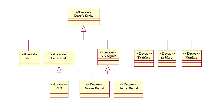
Each device is composed of an <<Entity>> class that contains all attributes and methods needed for the control of the device. For each device type, a specific sub-class is provided as shown in the following diagram:

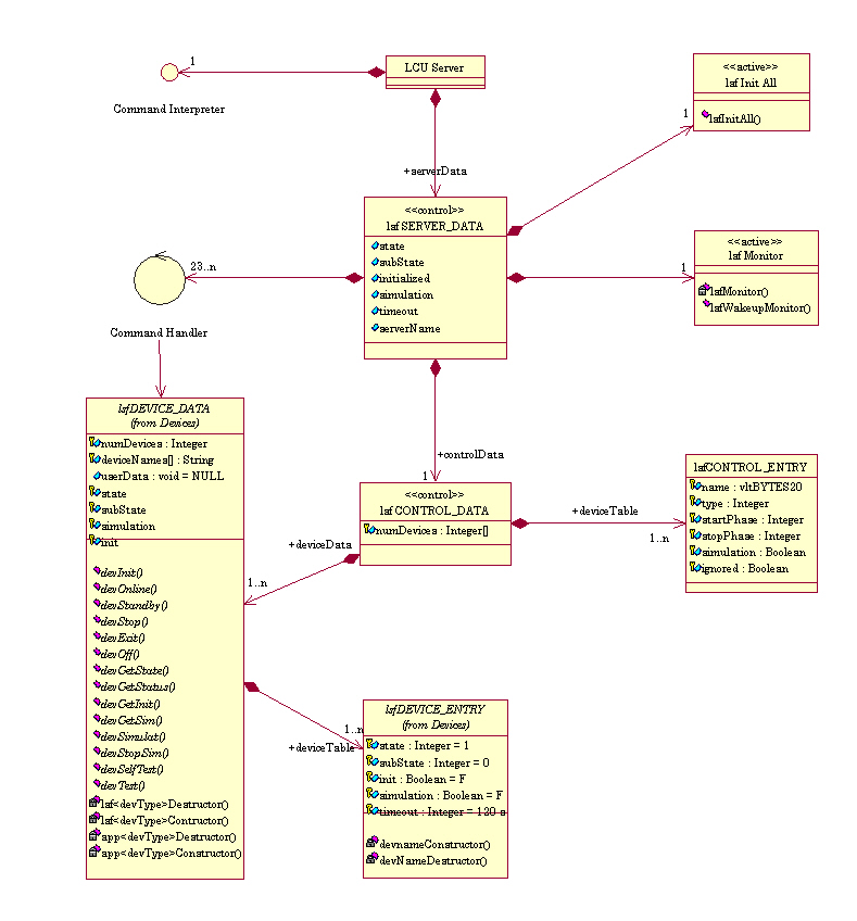
Each Software Device is mapped in the LCU database. The branch is structured as illustrated in the diagrams below. All classes derive from BASE_CLASS; this class provides the attribute access methods based on cai.

All the classes used for the database branch are derived from the generic device class lsfDB_DEVICE: this class contains the minimum set of attributes required for holding the device status information. As a consequence, any hardware device class contains these attributes plus the device specific configuration attributes.
The class lsfDB_CONTROL contains the deviceTable, that stores the global information related to all the controlled devices.
At instantiation, the point
:control contains one
sub-point per type of controlled device. These points are instantiated from
lsfDB_DEVICE so as to provide status
information of the group of devices of that kind.
The instances of all the devices of that type are grouped under this point
as shown in the diagram below:

The control flow of the standard commands is distributed over the 3 classes:
In addition 2 objects are provided:
The following diagram depicts the state machine of a Software Device for all Standard Commands and Specific Commands:

The sub-state Active is a generic denomination, that may be substituted by the appropriate sub-state(s) identified for the sub-system (e.g. Moving for a sub-system containing a motorized axis).
Each LCU Application shall run on one and only one LCU, which must encompass:
A standard LCU is connected to one LAN.
Optional support of a second LAN (as for Rapid Guiding) shall be granted.
The Workstation software environment consists of:
The LCU software environment consists of:
The LCU Server Framework implements the minimum behavior for all the Standard Commands. The following Use Case diagram depicts the functional requirements associated to the Standard Commands.

This diagram is a commonly accepted addition to the set of standard commands in terms of query and tool features. These commands do not involve any device and their function is rather simple, therefore will not be described in detail herein.

The Use Cases description is given in Appendix.
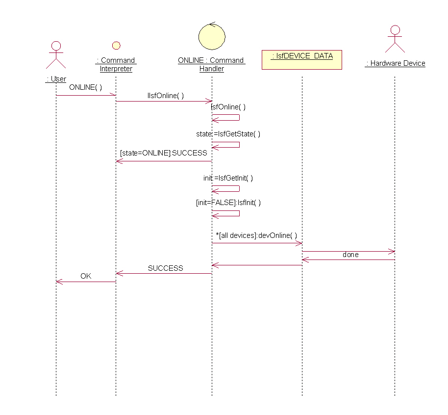
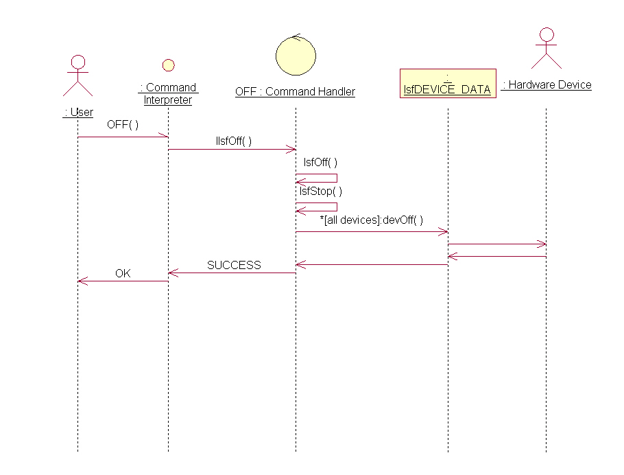
The following Sequence and Activity diagrams are shown below for each Standard Command.
The sub-system performs all necessary steps so as to initialize all its components to a known state.


The sub-system performs all necessary operations to bring all its components to a low power safe state.


The sub-system performs all necessary operations to bring all its components to full operational state.

The sub-system performs all necessary operations to stop activity on all its components.


The sub-system performs all necessary operations to release any connection to its components; the sub-system remains able to receive any command.

The sub-system software terminates its activity.


The query and tool commands STATE, STATUS, VERSION etc... shall be accepted in any state, but OFF
The sub-system performs a dedicated operation involving its components. Multiple instances of the same command shall be allowed in some cases as of the requirements, this command shall be processed as a task, whereby the task name is appended a unique running index.
In most cases, the sub-system state shall be ONLINE; in particular for all commands involving an activation of the components (e.g. moving a wheel). However, as of the state description, some commands shall be accepted while in STANDBY: any query command as well as any command related to this state are allowed (e.g. start/stop temperature monitoring, start/stop periodic wipe of a CCD chip).
The following Activity Diagram illustrates the skeleton of the control flow associated to a Specific Command.

The LCU Server Framework has the following benefits and liabilities:
This chapter is divided in two sections dedicated respectively to the effective implementation of the framework and to the usage of the framework for creating new Software Devices.
The implementation of the framework is independent of the programming language selected:
The effective implementation of the lsf
framework has been made in C.
The decision was taken considering following aspects:
Even though most of the instances of the LCU Server Framework are Singletons ([RD 08] page 122), the implementation of this Design Pattern is left to the developer; in fact, would the framework implement this pattern, it would not be possible for an application to create more than one instance.
The creation of a Software Device based on the framework has been made easy by means of a small set of adapted tools, see lsf(1), and the elaboration of the template module lsftpl as basis for the instanciation:
The class diagram below illustrates the instantiated class diagram for an example sub-system app, providing one specific command SPECMD. The Command Handler SPECMD implements the 2 methods IappDeviceSpecificCommand() and appDeviceSpecificCommand().

Example code of a Software Device is available via the command
lsfCreate app.
This new module can be immediately built and run on an LCU.
All the new sub-systems of the Auxiliary Telescopes: e.g. the Nasmyth Focus Devices.
Since its first release, all the new VLTI applications are based on LSF: the framework has become the de facto standard for any new LCU application (but the Instrumentation Software which bases on ICB):
An instance of the LCU Server Framework is often a Singleton, unless specified.