Device Manager (fcfDevmgr)
The Device Manager (fcfDevmgr) provides the functionality for supervision and management of a configurable set of devices.
The Device Manager provides a library of devices implementing the communication with the respective device controllers in the PLC. Devices are created at the manager start-up by a device factory class. The main components of the Device Manager server are:
State Machine engine based on SCXML and implemented in RAD. It contains a set of action and activity classes.
A Device Factory class that creates the instances of all device classes at start-up and based on the server configuration.
A set of Device classes. Each device has two additional classes: one for the device configuration and the other one for the interface with the Local Control System (LCS).
A Facade class that manages the interface between the state machine engine and the device classes.
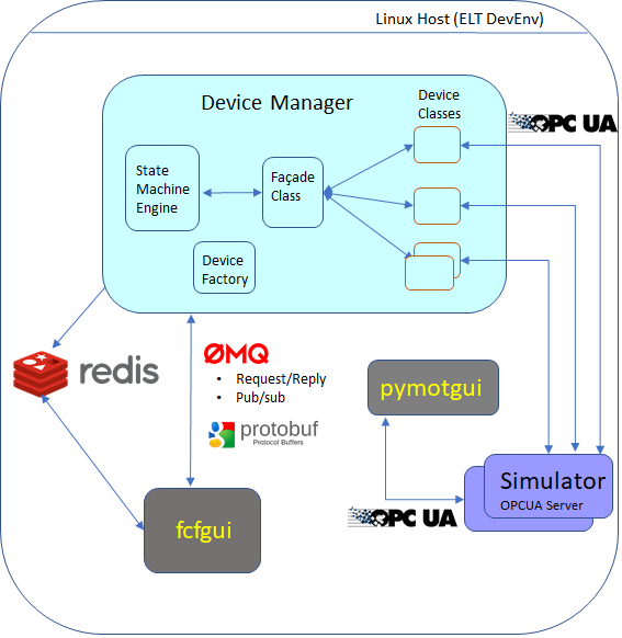
Device Manager Components without LCS.
Client applications, such as fcfGui, send commands to the Device Manager using the CII MAL library (request/reply). The fcfGui reads the information about the devices from the Redis DB using polling.
The Device Manager uses the Redis Database to store run-time information about itself and about the devices it controls. In absence of a Local Control System, device classes can connect to the Device Simulator via the OPC-UA protocol, see figure above.
In normal operation, device classes connect to the OPC-UA server running under the Windows OS side of the Beckhoff IPC, e.g .CX2030. This communication is based on the execution of RPC calls (OPC-UA Method profile). Each Device Controller running in the TwinCAT PLC declares a number of methods defining the interface with the Device Manager. Additionally, the device classes subscribe to the status data produced by the device controllers. Each time the status changes, the device classes are notified and they updates the Redis DB and publish the corresponding changes via CII (pub/sub).
The PLC OPC-UA Server connects to the device controllers via the vendor specific protocol (ADS). The device controllers trigger the changes in the hardware via the TwinCAT I/O mapping.
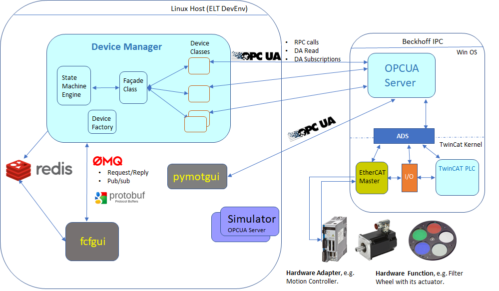
Device Manager connecting to a Beckhoff IPC.
Supported Devices
Shutters
The Shutter device is a general purpose device for controlling a shutter hardware function. The device can control the shutter open/close.
Lamps
The Lamp device is a general purpose device for controlling a lamp hardware function. The device can switch a lamp on/off, control the intensity and handle warm-up and cool-down times when this is supported.
Motors
The Motor device is a general purpose device that controls different types of motors. It provides the following features:
Support three different axis types: Linear, Circular and Circular-Optimized.
Note
Circular-Optimized means that the motor will always take the shorter path to reach the target position.
Definition of named positions in user units (UU) or encoder values.
Arbitrary positioning given in user units or encoder values.
Positioning in absolute or relative units.
Support for configurable Initialization Sequence.
Support for SW limits.
Support for various timeouts.
Auto disabling when standing.
Support for brake handling.
Support for backlash compensation.
IODev
The IODev device is a generic Input/Output control device that can be customized for specific applications not already covered by other devices. It can be configured with a variable number of channels. The IODev device supports three different input channel types: Digital input, Analog input and Integer input. And three different output channel types: Digital output, Analog output and Integer output.
Sensors
The Sensor is a IODev device configured only for monitoring signals. The Sensor device supports three different channel types: Digital input, Analog input and Integer input.
Derotators
The Derotator device is an aggregated motor device that continuously adapt its position according to the field or pupil rotation. It supports four different modes:
Stationary: Derotator moves to a target position based on the position angle and remains standstill after reaching the target.
Sky: The Derotator is continuously moving to compensate the field rotation.
Elevation: The Derotator is continuously moving to compensate the pupil rotation.
User: The Derotator is continuously moving according to a customized computation of the position defined by the user.
ADCs
The ADC device manages the position of two prisms with the aim of correcting for the atmospheric dispersion.
The device supports two modes:
Auto: The ADC is continuously positioning the two motors based on the telescope RA/DEC, the environmental parameters and the ADC configuration.
Off: The ADC moves to a target position and remains standstill after reaching the target.
Piezos
The ‘Piezo’ device manages the control of the output signals of a piezo hardware. It supports up to three axes. The device can be set in two modes:
Auto: The Piezo is correcting continuously the outputs based on the feedback signals.
- Pos: The Piezo set the output of the axes to a fixed value. In this mode, the Piezo can
be controlled in user positions (normally volts) or directly in bits.
Actuator
The Actuator device is a general purpose device for controlling actuators through a switch signal (on/off). The most common use of actuators is for power control.
SmarAct
These are motor devices handled by a SmarAct controller type.
MultiAxis
The multi-axis device is a generic device controlling multiple axis. Each axis is controlled with a motor device. We have now two flavours for this device. One with tracking capabilities and one without this feature.
PSU8600
This device controls a Siemens power supply (PSU8600) which requires some specific handling due to the special protections implemented by the PSU.
Device Manager State Machine
The Device Manager uses a state machine described in a SCXML format that is
interpreted by the state machine engine provided by the rad application framework.
(SCXML specification).
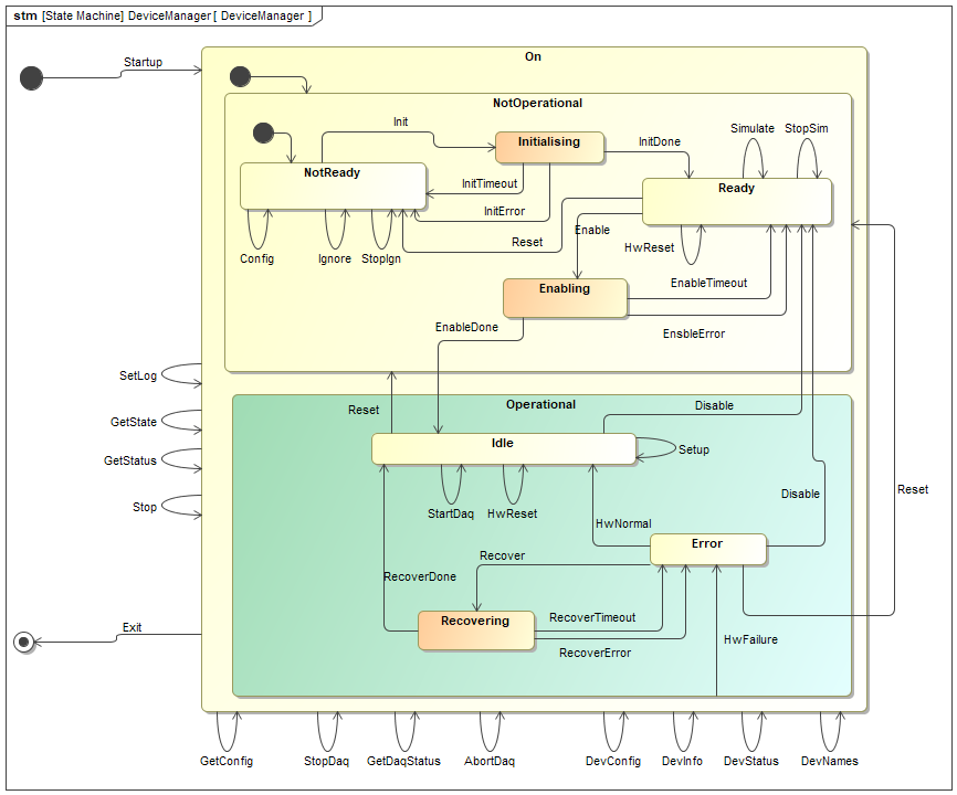
Device Manager State Machine Diagram.
Extract of the current State Machine specification for the Device Manager.
<state id="On">
<initial>
  <transition target="NotOperational"/>
</initial>
<state id="NotOperational">
  <initial>
    <transition target="NotReady"/>
  </initial>
  <state id="NotReady">
    <transition event="Events.Reset" target="NotReady">
       <customActionDomain:ActionReset name="ActionReset"/>
    </transition>
    <transition event="Events.Init" target="Initialising"/>
    <transition event="Events.Config">
     <customActionDomain:ActionConfig name="ActionConfig"/>
    </transition>
  </state>
  <state id="Initialising">
    <onentry>
      <customActionDomain:ActionInitStart name="ActionInitStart"/>
    </onentry>
    <invoke id="ActivityInitialising"/>
           <transition event="Events.InitDone" target="Ready">
              <customActionDomain:ActionInitDone name="ActionInitDone"/>
           </transition>
           <transition event="Events.InitError" target="NotReady">
              <customActionDomain:ActionInitError name="ActionInitError"/>
           </transition>
Command Line Arguments
Command line argument help is available under the option --help.
--server-id ARG| -i ARG(string)Server id. If not specified uses the one included in the configuration file.
--config ARG| -c ARG(string)Application configuration file (see fcf_device_config_ref for more details about the server configuration).
--log-level ARG| -l ARG(enum) [default: ERROR]Log level to use. One of ERROR, INFO, DEBUG, TRACE.
--log-prop-file ARG| -l ARG(string)Log property file.
--req-endpoint ARG| -l ARG(string)Server MAL Req/Rep endpoint (zpb.rr://<ipaddr>:<port>/).
Environment Variables
$CFGPATHUsed to resolve configuration file paths.
$DATAROOTSpecifies the default root path used as output directory for FITS metadata. Metadata files are stored under $DATAROOT/fcf/<fcs instance>.
Configuration
CII Configuration Service (config-ng)
The FCF in version 4.0.0 has been ported to the CII config-ng library. Unlike yaml-cpp, this library allows to define type information for the configuration parameters. The FCF has included a predefined set of configuration definitions. These files are part of the FCF configuration and can be found in the fcf/server/resources/config directory. This config directory contains the following subdirectories:
definitions: it contains the basic types for the server and devices.
mapping: it contains the instances of the mapping files for each device type.
devices: it contains examples of configuration for each device type.
server: it contains an example of the configuration for the server.
You can find more information about CII config-ng in the following link. (Config-ng manual).
Warning
Please note that due to the porting to the CII config service, all applications shall be updated accordingly.
Device Manager Configuration
The server configuration is a set of files written in yaml format.
(YAML specification). YAML is easy to read format
that has been adopted by the CII configuration service.
Many resources about YAML can be found on the web. One could also validate the format online, see http://yaml.org/spec/
The CII config-ng defines a set of yaml custom tags for defining types, e.g.
!cfg.type:int32 defines an integer parameter. Applications can define additional
types. The FCF has defined a number of types including one per device.
Note
The entry point for the Device Manager configuration is the file that contains the server configuration and the mapping to the device configuration files. The configuration of each device should be given in a separate file for better readability and maintenance. Each device type uses the corresponding mapping file that defines the real names of the attributes in the OPC-UA address space.
Config Item |
Type |
Optional |
Default |
Description |
|---|---|---|---|---|
server::server_id |
string |
no |
This is the id associated with the specific server. |
|
server::req_endpoint |
string |
no |
This is the endpoint for CII MAL request/reply. The server will listen to incoming commands using this endpoint. |
|
server::pub_endpoint |
string |
no |
This is the endpoint for CII MAL pub/sub. The server will publish its status using this endpoint. |
|
server::db_timeout |
double |
yes |
2000 [ms] |
This is the timeout for connecting to the Redis DB. Unit is milliseconds. |
server::log_properties |
string |
yes |
log4cplus property file to be used by the server. |
|
server::scxml |
string |
no |
This is the state machine specification file used by the server. |
|
server::fits_prefix |
string |
no |
This is the prefix to be used for the INS meta-data. |
|
server::oldb_prefix |
string |
no |
This is the prefix to be used for the DB. This prefix is meant to identify uniquely a given system, e.g. micado. |
|
server::req_timeout |
double |
yes |
2000 [ms] |
General command timeout for sending commands to the Local Control System (LCS). Unit is milliseconds. |
server::mon_timeout |
double |
yes |
1000 [ms] |
General timeout for monitoring. Unit is milliseconds. |
server::dictionaries |
string |
no |
Vector of dictionaries to be used by the server. |
|
server::devices |
devices |
no |
This is a vector of devices which are active in the server configuration. Only devices listed here will be managed by the server. |
|
server::gui::containers |
containers |
yes |
This is a vector of containers for the GUI. It defines the list of Docking Widgets to be created in the GUI to store widgets. Each element in the vector has a name and position (LEFT or RIGHT). This configuration parameter is only valid for the Python version of the FCF GUI. |
|
server::gui::tabify |
boolean |
yes |
true |
It automatically organizes docking widgets into tabs when they share the same position (LEFT or RIGHT). |
server::gui::widget_space |
uint32 |
yes |
true |
It defines a space between widgets inside the docking widget. Default value is zero. |
server::gui::shell_cmd |
string |
yes |
fcfcli |
It allows using a custom shell from the FCF GUI. Default value is fcfcli. |
server::gui::shell_params |
string |
yes |
It allows adding additional parameters to the shell that users can open from the FCF GUI, e.g. –log_level DEBUG |
Each element in the device vector has the following attributes:
Configuration |
Description |
Optional |
|---|---|---|
name |
This is the device name. |
No |
cfgfile |
Configuration filename for a device. |
No |
type |
Device type. |
No |
widget |
It defines the widget configuration by setting the following parameters: container, dimension and custom. This parameter is only relevant for the Python version of the FCF GUI. See more details in the description below. |
Yes |
Each element in the GUI Container vector has the following attributes:
Configuration |
Description |
Optional |
|---|---|---|
name |
This is the container name. |
No |
position |
This is the default position of the container on the FCF GUI (LEFT or RIGHT). |
Yes |
Each element in the Widget configuration has the following attributes:
Configuration |
Description |
Optional |
|---|---|---|
container |
It associates the device widget with a GUI container. This association means, the widget will appear inside this container. The container shall be one of the containers listed in the GUI Container vector. |
No |
dimension |
It defines the default dimension of the widget on the screen (currently not used). |
Yes |
custom |
It specifies the custom widget by indicating the Python library and the widget class to be used. The widget class should inherit from the |
Yes |
Each element in the Custom configuration has the following attributes:
library |
It specifies the library where the custom widget class can be found. |
No |
|---|---|---|
class |
It defines the widget class. The signature of the custom widget shall be according to the base class. |
No |
params |
Define an additional set of parameters using python dictionary literal syntax. |
Yes |
An example of a server configuration is provided below.
# server definition
!cfg.include fcf/devmgr/definitions/server.yaml:

server: !cfg.type:FcfServer
    server_id       : 'fcs1'
    req_endpoint    : "zpb.rr://127.0.0.1:12082/"
    pub_endpoint    : "zpb.ps://127.0.0.1:12345/"
    db_endpoint     : "127.0.0.1:6379"
    db_timeout      : 2000
    scxml           : "fcf/devmgr/server/sm.xml"
    dictionaries    : ["dictionary/dit/stddid/primary.did.yaml", "dictionary/fcf/devmgr/server/fcf.did"]
    log_properties  : "fcf/devmgr/server/log_properties.cfg"
    fits_prefix     : "INS1"
    oldb_prefix     : "ins8"
    req_timeout     : 300000
    devices         : [
    {
    name: 'shutter1',
    type: Shutter,
    cfgfile: "fcf/devmgr/devices/shutter1.yaml"
    },
    {
    name: 'lamp1',
    type: Lamp,
    cfgfile: "fcf/devmgr/devices/lamp1.yaml"
    },
    {
    name: 'actuator1',
    type: Actuator,
    cfgfile: "fcf/devmgr/devices/actuator1.yaml"
    },
    {
    name: 'motor1',
    type: Motor,
    cfgfile: "fcf/devmgr/devices/motor1.yaml"
    },
    {
    name: 'piezo1',
    type: Piezo,
    cfgfile: "fcf/devmgr/devices/piezo1.yaml"
    },
    {
    name: 'sensor1',
    type: Sensor,
    cfgfile: "fcf/devmgr/devices/sensor1.yaml"
    widget: {
     container: "Sensors",
     custom: {
        class: "TaurusSensorPlot",
        # WARNING: parameters shall be formatted using the python dictionary literal syntax.
        # You should check what are the allowed parameters supported by the custom class.
        # The parameters are passed as a dynamic keyword list (**kwargs).
        params: '{"view_size": 5, "ylabel":"[Celsius]", "title":"Temperatures", "axes":["ch4", "ch5"]}',
        library: "ifw.fcf.pyfcfgui.wdglib"
        }
      }
    },
    {
    name: 'adc1',
    type: Adc,
    cfgfile: "fcf/devmgr/devices/adc1.yaml"
    },
    {
    name: 'drot1',
    type: Drot,
    cfgfile: "fcf/devmgr/devices/drot1.yaml"
    }
    ]
Another example using GUI configuration parameters:
!cfg.include config/fcf/devmgr/definitions/server.yaml:

server: !cfg.type:FcfServer
    server_id       : 'fcs'
    req_endpoint    : "zpb.rr://127.0.0.1:12082/"
    pub_endpoint    : "zpb.ps://127.0.0.1:12345/"
    db_timeout      : 2000
    scxml           : "config/fcf/devmgr/server/sm.xml"
    dictionaries    : ['dictionary/dit/stddid/primary.did.yaml', 'dictionary/fcf/devmgr/server/fcf.did']
    fits_prefix     : "INS1"
    oldb_prefix     : 'elt/tins'
    req_timeout     : 120000
    log_properties  : "config/fcs/server/log_properties.cfg"
    version         : '0.0.0'
    gui: {
          containers: [
           {
             name: 'Devices',
             position: 'LEFT'
           },
           {
             name: 'Sensors',
             position: 'RIGHT'
           }
         ]
       }
    devices         : [
    {
    name: 'shutter1',
    type: Shutter,
    cfgfile: "local/shutter1.yaml"
    },
    {
    name: 'lamp1',
    type: Lamp,
    cfgfile: "local/lamp1.yaml"
    },
    {
    name: 'motor1',
    type: Motor,
    cfgfile: "local/motor1.yaml"
    },
    {
    name: 'iodev1',
    type: IODev,
    cfgfile: "local/iodev1.yaml",
    widget: {
          container: "Sensors"
        }
    },
    {
    name: 'mirror1',
    type: Mirror,
    cfgfile: "local/mirror1.yaml",
    widget: {
          custom: {
             library: "tins.fcs.pyfcsgui.wdglib.taurusmirror",
             class: "TaurusMirror"
          },
          container: "Devices"
        }
    }
    ]
Device Base Configuration
Each device has a common set of configuration parameters.
Note
address has been renamed to dev_endpoint in version 4.0.0.
Note
simaddr has been renamed to sim_endpoint in version 4.0.0.
An example of a mapping file configuration is included below.
!cfg.include fcf/devmgr/definitions/shutterMap.yaml:

Shutter: !cfg.type:ShutterMap
   cfg:
      low_closed:     cfg.bActiveLowClosed
      low_fault:      cfg.bActiveLowFault
      low_open:       cfg.bActiveLowOpen
      low_switch:     cfg.bActiveLowSwitch
      ignore_closed:  cfg.bIgnoreClosed
      ignore_fault:   cfg.bIgnoreFault
      ignore_open:    cfg.bIgnoreOpen
      initial_state:  cfg.bInitialState
      timeout:        cfg.nTimeout
   stat:
      state:         stat.nState
      substate:      stat.nSubstate
      local:         stat.bLocal
      error_code:    stat.nErrorCode
   rpc:
      rpcInit:       RPC_Init
      rpcEnable:     RPC_Enable
      rpcDisable:    RPC_Disable
      rpcClose:      RPC_Close
      rpcOpen:       RPC_Open
      rpcStop:       RPC_Stop
      rpcReset:      RPC_Reset
Note
With the information contained in the mapping file, combined with the PLC prefix and the namespace, the device obtains the NodeId for each of the attributes and the RPCs defined in the ICD with the device controller. NodeIds are assuming to have string format.
Note
In IFW v6.0.0, it has been added the support for the Node ID representation. The Node ID is represented by the string “ns=<namespace index>;i|s|g=<identifier>”. This has been motivated to support some commercial OPC-UA servers that do not support the string representation. It is recommended to use the Node ID format only when it would be strictly needed.
Shutter Specific Configuration
The Shutter device defines a set of configuration parameters that will be transferred
to the device controller running in the LCS (PLC). All these parameters are under the
ctrl_config heading.
Warning
The ctrl_config parameters are downloaded to the device controller when the device is not Operational. If the controller is already Operational, the user shall force the transition from Operational to NotOperational/NotReady and back to Operational.
Config Item |
Type |
Optional |
Default |
Description |
|---|---|---|---|---|
ctrl_config::low_closed |
bool |
yes |
false |
If true, the closed signal is active low. |
ctrl_config::low_fault |
bool |
yes |
false |
If true, the fault signal is active low. |
ctrl_config::low_open |
bool |
yes |
false |
If true, the open signal is active low. |
ctrl_config::low_switch |
bool |
yes |
false |
If true, the switch signal is active low. |
ctrl_config::ignore_closed |
bool |
yes |
false |
If true, the closed signal is ignored. |
ctrl_config::ignore_fault |
bool |
yes |
false |
If true, the fault signal is ignored. |
ctrl_config::ignore_open |
bool |
yes |
false |
If true, the open signal is ignored. |
ctrl_config::initial_state |
bool |
yes |
false |
If true, the initial state for shutter will be open. |
ctrl_config::timeout |
uint |
yes |
3000 [ms] |
Shutter timeout for transitions. Unit is milliseconds. |
An example of a shutter configuration is given below.
!cfg.include fcf/devmgr/definitions/shutter.yaml:

# Please note some parameters are inherited and therefore not defined here.
shutter1: !cfg.type:Shutter
  identifier: PLC1                             # OPCUA Object Identifier
  prefix: MAIN.Shutter1                        # OPCUA attribute prefix
  simulated: true
  dev_endpoint: opc.tcp://134.171.59.98:4
  sim_endpoint: opc.tcp://127.0.0.1:7576            # Simulation address
  fits_prefix: "SHUT1"
  ctrl_config: !cfg.type:ShutterController
     initial_state:  false                              # If T, initial state is open
Lamp Specific Configuration
The Lamp device defines a set of configuration parameters that will be transferred
to the device controller running in the LCS (PLC). All these parameters are under the
ctrl_config heading.
Warning
The ctrl_config parameters are downloaded to the device controller when the device is not Operational. If the controller is already Operational, the user shall force the transition from Operational to NotOperational/NotReady and back to Operational.
Config Item |
Type |
Optional |
Default |
Description |
|---|---|---|---|---|
ctrl_config::low_fault |
bool |
yes |
false |
If true, the fault signal is active low. |
ctrl_config::low_on |
bool |
yes |
false |
If true, the on signal is active low. |
ctrl_config::low_switch |
bool |
yes |
false |
If true, the switch signal is active low. |
ctrl_config::ignore_fault |
bool |
yes |
false |
If true, the fault signal is ignored. |
ctrl_config::invert_analog |
bool |
yes |
false |
If true, the analog feedback is active. |
ctrl_config::initial_state |
bool |
yes |
false |
If true, the initial state will be switched on. |
ctrl_config::analog_threshold |
int |
yes |
0 [bits] |
Analog feedback signal threshold |
ctrl_config::analog_range |
uint |
yes |
32767 |
Full range of A/D converter for analog output. |
ctrl_config::cooldown |
uint |
yes |
0 [s] |
Cooldown time. Unit is seconds. |
ctrl_config::maxon |
uint |
yes |
0 [s] |
Maximum time for the lamp to be On. If value is zero means no maximum is defined. Unit is seconds. |
ctrl_config::warmup |
uint |
yes |
0 [s] |
Warmup time. Unit is seconds. |
ctrl_config::timeout |
uint |
yes |
3000 [ms] |
Lamp timeout for transitions. Unit is milliseconds. |
An example of a lamp configuration is given below. This configuration file can be found in module devmgr/server
!cfg.include fcf/devmgr/definitions/lamp.yaml:

# Please note some parameters are inherited and therefore not defined here.
lamp1: !cfg.type:Lamp
  identifier: PLC1                             # OPCUA Object Identifier
  prefix: MAIN.Lamp1                           # OPCUA attribute prefix
  dev_endpoint: opc.tcp://134.171.59.98:4840
  sim_endpoint: opc.tcp://134.171.12.182:4840
  fits_prefix: "LAMP1"
  ctrl_config:
     initial_state:    false                     # If T, initial state is on
IODev Specific Configuration
The iodev devices defines currently no configuration that will be downloaded to the LCS. However, it defines the configuration of the iodev channels. The sensor channels are known only at the server side.
Config Item |
Type |
Optional |
Default |
Description |
|---|---|---|---|---|
norpc |
bool |
yes |
false |
Flag to indicate that the device does not support RPCs. This means, no RPC calls to change the state will be executed. This flag is used for special devices running in commercial controllers not running in a PLC but having an embedded OPC-UA server. To be used only in special cases. |
sensor |
bool |
yes |
false |
Flag to indicate that the iodev is a sensor device. When this flag is active, the iodev only monitors input channels. This is the most typical usage of the iodev device. |
ctrl_config::timeout |
uint |
yes |
3000 [ms] |
Sensor timeout for transitions. Unit is milliseconds. |
channels |
channels |
no |
na |
List of channels. |
Each channel contains the following configuration parameters:
Config Item |
Type |
Optional |
Default |
Description |
|---|---|---|---|---|
name |
string |
no |
“” |
Channel name. |
description |
string |
yes |
“” |
Channel description. |
type |
string |
no |
na |
Channel type. Allowed types for input channels:
Allowed types for output channels:
|
header |
bool |
yes |
true |
If true, the channel will be included in the metadata FITS file. |
log |
bool |
yes |
true |
If true, the sensor value will be logged (Not available yet !). |
map |
string |
no |
na |
Channel internal mapping to the name in the LCS. |
named_values |
vector |
no |
na |
Vector of pair name/values. Named values associate specific sensor raw values to names. |
prefix |
string |
no |
na |
Channel FITS prefix. |
unit |
string |
yes |
na |
Channel unit. |
Warning
The channels parameter has been modified in version 4.0.0 with the porting to the CII config-ng.
An example of a sensor configuration is given below. This configuration file can be found in module devmgr/server. In this case, the sensor device has two channels: ch1 and ch2.
!cfg.include fcf/devmgr/definitions/sensor.yaml:
# Please note some parameters are inherited and therefore not defined here.

sensor1: !cfg.type:Sensor
   identifier: PLC1
   prefix: MAIN.IODev1
   dev_endpoint: opc.tcp://134.171.59.98:4840
   sim_endpoint: opc.tcp://134.171.57.209:4840
   fits_prefix: "SENSOR1"
   ctrl_config:
      timeout:         20000
   channels: [
   {
    name: ch1,
    description: "channel1",
    fits_prefix: "CH1 STAT",
    type: DI,
    header: true,
    log: true,
    unit: mm,
    map: di1,
    named_values: [
    {
      name: 'HIGH',
      value: '1'
    },
    {
      name: 'LOW',
      value: '0'
    }
    ]
    },
    {
    name: ch2,
    description: "channel2",
    fits_prefix: "CH2 STAT",
    type: DI,
    header: true,
    log: true,
    unit: dd,
    map: di2
    }
    ]
Psu8600 Specific Configuration
The Psu8600 does not have any specific configuration and therefore uses the one from IODev. An example of a Psu8600 configuration is given below. This configuration file can be found in module devmgr/server.
cfg.include config/fcf/devmgr/definitions/psu8600.yaml:

psu1: !cfg.type:Psu8600
    mapfile: "config/fcf/devmgr/mapping/psu8600.yaml"
    dev_endpoint: opc.tcp://10.207.239.197:4840
    sim_endpoint: opc.tcp://10.207.239.197:4840
    fits_prefix: "SENSOR1"
    norpc: true
    sensor: false
    identifier: "ns=3;i=101069"
    prefix: ""
    channels: [
    {
    name: output1,
    description: "output1",
    fits_prefix: "CH1 STAT",
    type: DO,
    unit: "",
    map: do1,
    named_values: [
        {
        name: 'ON',
        value: '1'
        },
        {
        name: 'OFF',
        value: '0'
        }
        ]
    }
    ]
Motor Specific Configuration
The Motor device defines a set of configuration parameters that will be transferred
to the device controller running in the LCS (PLC). These parameters are under the
ctrl_config heading. The motor initialisation sequence will be also downloaded to
the LCS.
The motor also defines a set of configuration parameters that are only known at the server level, for instance the named positions of the motor.
Tolerance of the named position in user units (UU). If the actual position is within the tolerance, the device will report the named position otherwise its name will be empty.
Warning
The ctrl_config parameters are downloaded to the device controller when the device is not Operational. If the controller is already Operational, the user shall force the transition from Operational to NotOperational/NotReady and back to Operational.
Config Item |
Type |
Optional |
Default |
Description |
|---|---|---|---|---|
axis_type |
string |
yes |
LINEAR |
Axis type. Allowed options are: LINEAR, CIRCULAR and CIRCULAR_OPT. |
tolerance |
double |
yes |
1 [uu] |
Tolerance of the named position in user units (UU). If the actual position is in the tolerance, the device will report the named position otherwise its name will be empty. |
positions |
vector of positions |
no |
na |
Vector of named positions, see description below. |
initialisation |
vector of steps |
no |
na |
Vector of initialisation steps, see description below. |
ctrl_config::min_pos |
double |
yes |
0 [uu] |
Minimum position in user units. |
ctrl_config::max_pos |
double |
yes |
0 [uu] |
Maximum position in user units. |
ctrl_config::velocity |
double |
yes |
1.0 [uu/s] |
Default velocity for moving the motor in position mode |
ctrl_config::active_low_lstop |
bool |
yes |
false |
If true, the Lower Stop signal is active low. |
ctrl_config::active_low_lhw |
bool |
yes |
false |
If true, the Lower Hw signal is active low. |
ctrl_config::active_low_ref |
bool |
yes |
false |
If true, the Reference signal is active low. |
ctrl_config::active_low_index |
bool |
yes |
false |
If true, the Index signal is active low. |
ctrl_config::active_low_ustop |
bool |
yes |
false |
If true, the Upper Stop signal is active low. |
ctrl_config::active_low_uhw |
bool |
yes |
false |
If true, the Upper Hw signal is active low. |
ctrl_config::exec_pre_init |
bool |
yes |
false |
If true, the pre-init execution is activate |
ctrl_config::exec_post_init |
bool |
yes |
false |
If true, the post-init execution is activate. |
ctrl_config::exec_pre_move |
bool |
yes |
false |
If true, the pre-move execution is activate. |
ctrl_config::exec_post_move |
bool |
yes |
false |
If true, the post-move execution is activate. |
ctrl_config::low_brake |
bool |
yes |
false |
If true, the Brake signal is active low. |
ctrl_config::low_inpos |
bool |
yes |
false |
If true, the In Position signal is active low. |
ctrl_config::backlash |
double |
yes |
0 [uu] |
Backlash compensation. If value is zero means no backlash compensation is active. |
ctrl_config::disable |
bool |
yes |
false |
If true, the power of the motor will be disabled after positioning. |
ctrl_config::lock |
bool |
yes |
false |
If true, the motor position will be locked |
ctrl_config::lock_pos |
double |
yes |
0 [uu] |
Position that will be locked in case lock configuration is activated. |
ctrl_config::lock_tolerance |
double |
yes |
0 [us] |
Tolerance of the lock position |
ctrl_config::init_timeout |
int |
yes |
60000 [ms] |
Motor initialisation timeout. Unit is milliseconds. |
ctrl_config::move_timeout |
int |
yes |
60000 [ms] |
Motor move timeout. Unit is milliseconds. |
ctrl_config::switch_timeout |
int |
yes |
150000 [ms] |
Motor timeout for going out of the switch during initialisation. Unit is milliseconds. |
Note
An optional parameter in this context means that FCF provides a default value in the parent device type configuration. This default value will be used unless users redefine it in the device instance configuration.
Motor Initialisation
Note
The motor has a set of configuration parameters dedicated to the motor initialisation sequence. The initialisation sequence is downloaded to the LCS only when device controller is not operational.
Note
In case parameters are not applicable (na) please use 0 instead, for instance END, 0, 0
Step |
Description |
Parameter 1 |
Parameter 2 |
|---|---|---|---|
END |
Finish the sequence, no more actions are performed. |
na |
na |
FIND_INDEX |
Motor moves until finding the index pulse. |
Fast velocity [UU/s] |
Slow velocity [UU/s] |
FIND_REF_LE |
Motor moves until finding lower edge of reference switch. |
Fast velocity [UU/s] |
Slow velocity [UU/s] |
FIND_REF_UE |
Motor moves until finding upper edge of reference switch. |
Fast velocity [UU/s] |
Slow velocity [UU/s] |
FIND_LHW |
Motor moves until finding lower hardware limit. |
Fast velocity [UU/s] |
Slow velocity [UU/s] |
FIND_UHW |
Motor moves until finding upper hardware limit. |
Fast velocity [UU/s] |
Slow velocity [UU/s] |
DELAY |
Motor wait for a fixed amount of time before to continue. |
time in [ms] |
na |
MOVE_ABS |
Motor moves to an absolute position. |
Velocity [UU/s] |
Target position [UU] |
MOVE_REL |
Motor moves to a relative position. |
Velocity [UU/s] |
Target position [UU] |
CALIB_ABS |
Motor calibrates an absolute position. |
Position [UU] |
na |
CALIB_REL |
Motor calibrates a relative position. |
Position [UU] |
na |
CALIB_SWITCH |
Motor calibrates switch position. |
Position [UU] |
na |
Note
Some of the initialisation steps require parameters, for instance the speed of the motor. These parameters are defined together with the initialisation step.
Named Positions
The motor device supports a configuration of named positions that associate specific motor position in user units (UU) to names. The aim of name positions is to facilitate the setting of motor positions by end users.
Note
One example of a motor configuration is given below. This configuration file can be found in module devmgr/server. Another example using position types is also included.
!cfg.include fcf/devmgr/definitions/motor.yaml:

# Please note some parameters are inherited and therefore not defined here.
motor1: !cfg.type:Motor
  identifier: PLC1                             # OPCUA Object Identifier
  prefix: MAIN.Synchro1                        # OPCUA attribute prefix
  dev_endpoint: opc.tcp://134.171.59.98:4840
  sim_endpoint: opc.tcp://134.171.57.209:4840       # Simulation address
  fits_prefix: "MOT1"
  ctrl_config:
     velocity:              3.0
     min_pos:               0.0
     max_pos:               359.0
     active_low_ref:        true
     active_low_uhw:        true
  initialisation: [
     {
      step: 'FIND_LHW',
      value1: 4.0,
      value2: 4.0
     },
     {
      step: 'FIND_UHW',
      value1: 4.0,
      value2: 4.0
     },
     {
      step: 'CALIB_ABS',
      value1: 0.0,
      value2: 0.0
     },
     {
      step: 'END',
      value1: 0.0,
      value2: 0.0
     }
   ]
  positions: [
   {
    name: 'ON',
    value: 30
   },
   {
    name: 'OFF',
    value: 100
    }
   ]
Motor configuration example using position type, id and slot number.
!cfg.include config/ifw/fcf/devmgr/definitions/motor.yaml:

# Please note some parameters are inherited and therefore not defined here.
motor1: !cfg.type:Motor
 identifier: PLC1
 prefix: MAIN.Synchro2
 dev_endpoint: opc.tcp://134.171.59.99:4840
 sim_endpoint: opc.tcp://127.0.0.1:7578
 fits_prefix: "OPTI1"
 axis_type:             CIRCULAR
 initialisation: [
     {
      step: 'FIND_LHW',
      value1: 4.0,
      value2: 4.0
     },
     {
      step: 'FIND_UHW',
      value1: 4.0,
      value2: 4.0
     },
     {
      step: 'CALIB_ABS',
      value1: 0.0,
      value2: 0.0
     },
     {
      step: 'END',
      value1: 0.0,
      value2: 0.0
     }
   ]
 positions: [
   {
    name: 'ON_NAME',
    value: 30,
    type: 'MASK',
    id: 'POS1',
    no: 1
   },
   {
    name: 'OFF_NAME',
    value: 100
    }
   ]

 ctrl_config:
    velocity:              3.0
    min_pos:               0.0
    max_pos:               359.0
    active_low_ref:        true
    active_low_uhw:        true
Motor Control
Motors like the other devices are controlled using the Setup command, for more detailed see here: fcf_devmgr_setup_command_ref.
Unit Handling
Motors can be controlled using User Unit (UU) or encoder units. The user units, as well as the motor scale are defined in the axis configuration coming from the LCS. THe conversion from encoder to user units is done by the Device Manager based on the motor scale. Since the motor device is generic, user units may be different across different motorized devices. For instance linear motors are usually in millimeters while circular motors are in degrees.
Note
In version 5.0.0, the IFW added the possibility to control motors in SI units to comply with the ELT project requirement. Which SI units to use will anyway depend of each motor.
From version 5.0, the FCF also supports SI units. When you specify this unit, the Device Manager will convert the motor target position in SI to the motor User Units according to the configuration of the motor axis. The selection of the SI units will depend on the motor axis units. For instance, if a motor is a circular one, the Device Manager is assuming that the SI units are in radians. However if a motor is linear, the Device Manager will assume the SI units are in meters.
Derotator Specific Configuration
As for other devices, the Derotator device defines a set of configuration
parameters that will be transferred to the device controller running in the LCS
(PLC). All these parameters are under the ctrl_config heading.
Since the Derotator is just an aggregated motor device, it includes all Motor configuration parameters (see fcf_devmgr_motor_config_ref) plus a few parameters specific to derotators.
Warning
The ctrl_config parameters are downloaded to the device controller when the device is not Operational. If the controller is already Operational, the user shall force the transition from Operational to NotOperational/NotReady and back to Operational.
Config Item |
Type |
Optional |
Default |
Description |
|---|---|---|---|---|
ctrl_config::dir_sign |
int |
yes |
1 |
Motor direction sign |
ctrl_config::focus_sign |
int |
yes |
-1 |
Focus direction sign. |
ctrl_config::trk_period |
int |
yes |
20 [ms] |
Period of the tracking corrections within the PLC. |
ctrl_config::stat_ref |
double |
yes |
0.0 [uu] |
Reference position for stationary mode. |
ctrl_config::sky_ref |
double |
yes |
0.0 [uu] |
Reference position for sky mode. |
ctrl_config::user_ref |
double |
yes |
0.0 [uu] |
Reference position for user mode. |
ctrl_config::user_par1 |
double |
yes |
0.0 |
Specific parameter 1 for user mode. |
ctrl_config::user_par2 |
double |
yes |
0.0 |
Specific parameter 2 for user mode. |
ctrl_config::user_par3 |
double |
yes |
0.0 |
Specific parameter 3 for user mode. |
ctrl_config::user_par4 |
double |
yes |
0.0 |
Specific parameter 4 for user mode. |
Note
An example of a Derotator configuration is given below. This configuration file can be found in module devmgr/server.
!cfg.include fcf/devmgr/definitions/drot.yaml:

# Please note some parameters are inherited and therefore not defined here.
drot1: !cfg.type:Drot
    identifier: PLC1                             # OPCUA Object Identifier
    prefix: MAIN_FAST.drot                       # OPCUA attribute prefix
    dev_endpoint: opc.tcp://134.171.59.98:4840
    sim_endpoint: opc.tcp://134.171.57.209:4840       # Simulation address
    fits_prefix: "DROT1"
    initialisation: [
     {
      step: 'END',
      value1: 0.0,
      value2: 0.0
     }
     ]
    positions: [
     {
     name: 'ON',
     value: 30
     },
     {
     name: 'OFF',
     value: 100
     }
     ]
    ctrl_config:
        velocity:              3.0
        active_low_ref:        true
        active_low_uhw:        true
Note
The derotator uses Circular Optimize (CIRCULAR_OPT) as axis type. In this axis mode you have to reset the software limits to zero or simply not define them.
Derotator Control
Operation modes
Alias |
Name |
Description |
|---|---|---|
eng |
Engineering |
In this mode, the Derotator behaves like a standard motor. This means that it can be moved in user units and encoders. |
stat |
Stationary |
In this mode, the Derotator is stationary and it can be positioned at given angle according to the following formula: pos := stat_ref + dir_sign * (posang)/2.0; |
sky |
Sky |
The Derotator tracks following the field rotation. fieldRotation := parallactic - focus_sign * altitude; pos := sky_ref + dir_sign * (posang - fieldRotation)/2; angleOnSky := posang; modeAngle := angleOnSky; |
elev |
Elevation |
The Derotator tracks following the pupil rotation. pos := elev_ref + (focus_sign * dir_sign * altitude) /2.0; angleOnSky := parallactic; modeAngle := angleOnSky; |
user |
User |
The Derotator tracks according to the user custom computation. |
ADC Specific Configuration
As for other devices, the ADC device defines a set of configuration
parameters that will be transferred to the device controller running in the LCS
(PLC). These parameters are under the ctrl_config heading. Considering that
the ADC is a multi-axis device, it includes as well the configuration of two
standard motor devices. The configuration of each motor device is defined
in separate files and they correspond to the configuration of a standard motor
device (see fcf_devmgr_motor_config_ref).
Warning
The ctrl_config parameters are downloaded to the device controller when the device is not Operational. If the controller is already Operational, the user shall force the transition from Operational to NotOperational/NotReady and back to Operational.
Config Item |
Type |
Optional |
Default |
Description |
|---|---|---|---|---|
ctrl_config::motors |
vector |
no |
Vector of motors controlled by the ADC. See the table below. |
|
ctrl_config::trk_period |
int |
yes |
20 [ms] |
Period of the tracking corrections within the PLC. |
ctrl_config::pslope |
double |
yes |
0.0023 [arcsec/mbar] |
Pressure slope. |
ctrl_config::poffset |
double |
yes |
743.0 [mbar] |
Pressure offset. |
ctrl_config::tslope |
double |
yes |
-0.0061 [arcsec/C] |
Temperature slope. |
ctrl_config::toffset |
double |
yes |
12 [C] |
Temperature offset. |
ctrl_config::afactor |
double |
yes |
3.32 [1/arcsec] |
A Factor |
ctrl_config::zdlimit |
double |
yes |
0.0174533 |
Zenith distance limit |
ctrl_config::minelev |
double |
yes |
27.64 [deg] |
Minimum Elevation. |
ctrl_config::mot1_signoff |
int |
yes |
1 |
Motor 1 sign for off mode |
ctrl_config::mot1_signauto |
int |
yes |
1 |
Motor 1 sign for auto mode |
ctrl_config::mot1_signphi |
int |
yes |
1 |
Motor 1 sign for phi |
ctrl_config::mot1_refoff |
double |
yes |
0 [deg] |
Motor 1 offset for off mode |
ctrl_config::mot1_refauto |
double |
yes |
0 [deg] |
Motor 1 offset for auto mode |
ctrl_config::mot1_coffset |
double |
yes |
1.7387 [arcsec] |
Motor 1 C parameter |
ctrl_config::mot1_poffset |
double |
yes |
90 [deg] |
Motor 1 Position offset |
ctrl_config::mot1_drotfactor |
double |
yes |
2 |
Motor 1 derotator offset |
ctrl_config::mot2_signoff |
int |
yes |
1 |
Motor 2 sign for off mode |
ctrl_config::mot2_signauto |
int |
yes |
1 |
Motor 2 sign for auto mode |
ctrl_config::mot2_signphi |
int |
yes |
1 |
Motor 2 sign for phi |
ctrl_config::mot2_refoff |
double |
yes |
0 [deg] |
Motor 2 reference position for off mode |
ctrl_config::mot2_refauto |
double |
yes |
0 [deg] |
Motor 2 reference position for auto mode |
ctrl_config::mot2_coffset |
double |
yes |
1.7387 [arcsec] |
Motor 2 C parameter |
ctrl_config::mot2_poffset |
double |
yes |
90 [deg] |
Motor 2 Position offset |
ctrl_config::mot2_drotfactor |
double |
yes |
2 |
Motor 2 derotator offset |
Each element in the motor vector has the following parameters:
Config Item |
Type |
Optional |
Default |
Description |
|---|---|---|---|---|
name |
string |
no |
Name of the motor configuration. |
|
prefix |
string |
no |
Internal name used by the ADC for motor1 (fixed) |
|
cfgfile |
string |
no |
File path for the motor configuration. |
|
Note
An example of an Adc configuration is given below. This configuration file can be found in module devmgr/server.
!cfg.include fcf/devmgr/definitions/adc.yaml:

# Please note some parameters are inherited and therefore not defined here.
adc1: !cfg.type:Adc
    identifier: PLC1                             # OPCUA Object Identifier
    prefix: MAIN_FAST.adc                       # OPCUA attribute prefix
    dev_endpoint: opc.tcp://134.171.59.98:4840
    sim_endpoint: opc.tcp://134.171.57.209:4840       # Simulation address
    fits_prefix: "ADC1"
    ctrl_config:
    motors: [
    {
        name: 'adc1_motor1',
        prefix: "motor1",
        cfgfile: "fcf/devmgr/devices/adc1Motor1.yaml"
    },
    {
        name: 'adc1_motor2',
        prefix: "motor2",
        cfgfile: "fcf/devmgr/devices/adc1Motor2.yaml"
    }
    ]
ADC Control
Operation modes
The ADC operates two motorized functions. In engineering mode, each motor can be controlled independently.
Alias |
Name |
Description |
|---|---|---|
eng |
Engineering |
In this mode, the ADC behaves like the standard motor. This means that each motor can be moved in user units and encoders. |
off |
Off |
In this mode, the ADC is stationary and it can be positioned at given angle according to the following formula: pos := off_ref + sign_off * posang; |
auto |
Auto |
The ADC tracks following the default formula. This formula can be replaced by the user in order to accommodate instrument specific requirements. |
MAxis Specific Configuration
The MultiAxis device allows to control multiple axis like the ADC. However in this case, the device does not provide tracking capabilities. The configuration of each motor device is defined in separate files and they correspond to the configuration of a standard motor device (see fcf_devmgr_motor_config_ref).
Config Item |
Type |
Optional |
Default |
Description |
|---|---|---|---|---|
ctrl_config::motors |
vector |
no |
Vector of motors controlled by the ADC. See the table below. |
|
tolerance |
double |
yes |
1 [uu] |
Tolerance of the named position in user units (UU). If the actual position is in the tolerance, the device will report the named position otherwise its name will be empty. |
Each element in the motor vector has the following parameters:
Config Item |
Type |
Optional |
Default |
Description |
|---|---|---|---|---|
name |
string |
no |
Name of the motor configuration. |
|
prefix |
string |
no |
Internal name used by the ADC for motor1 (fixed) |
|
cfgfile |
string |
no |
File path for the motor configuration. |
|
Note
An example of an MAxis configuration is given below. This configuration file can be found in module devmgr/server.
!cfg.include fcf/devmgr/definitions/maxis.yaml:

# Please note some parameters are inherited and therefore not defined here.
maxis1: !cfg.type:MAxis
    overview: 'MAxis device example 1'
    description: "MAxis device example 1 description"
    identifier: PLC1
    prefix: MAIN_FAST.maxis
    dev_endpoint: opc.tcp://134.171.59.99:4840
    sim_endpoint: opc.tcp://127.0.0.1:7578
    fits_prefix: "OPTI1"
    motors         : [
    {
    name: 'maxis1_motor1',
    prefix: 'motor1',
    cfgfile: "config/fcf/devmgr/devices/maxis1Motor1.yaml"
    },
    {
    name: 'maxis1_motor2',
    prefix: 'motor2',
    cfgfile: "config/fcf/devmgr/devices/maxis1Motor2.yaml"
    }
    ]
MAxis Control
The MAxis allows for the control of individual axes as if they were standard motors, utilizing existing functionalities such as absolute and relative motion. Additionally, all axes can be moved simultaneously to a specified position or by using a named position. The actions associated with setting up this device are listed in the table below. These actions require completing the setup parameters for the device according to the interface definition. For more details, refer to the Setup Interface Definition.
ACTION |
Description |
|---|---|
MAXIS_MOVE_REL |
This action is used to move one individual axis in relative position. |
MAXIS_MOVE_ABS |
This action is used to move one individual axis in absolute position. |
MAXIS_MOVE_BY_NAME |
This action is used to move one individual axis using a named position. |
MAXIS_MOVE_BY_SPEED |
This action is used to move by speed one individual axis. |
MAXIS_MOVE_AXES |
This action is used to move all axes at once. |
MAXIS_MOVE_AXES_BY_NAME |
This action allows to move all axes based on a named position. |
MAXIS_MOVE_USER |
This action can be used when the position of individual axes need to be derived from a user position. |
MAXIS_CUSTOM |
This is a custom action that can be used for special purposes. |
MAtrk Specific Configuration
The MAtrk is another MultiAxis device whose main difference with the MAxis is that is meant for tracking devices. As for the MAxis, the configuration of each motor device is defined in separate files and they correspond to the configuration of a standard motor device (see fcf_devmgr_motor_config_ref).
Config Item |
Type |
Optional |
Default |
Description |
|---|---|---|---|---|
ctrl_config::motors |
vector |
no |
Vector of motors controlled by the ADC. See the table below. |
|
modes |
vector |
no |
[] |
Vector of modes supported by the device. |
tolerance |
double |
yes |
1 [uu] |
Tolerance of the named position in user units (UU). If the actual position is in the tolerance, the device will report the named position otherwise its name will be empty. |
Each element in the motor vector has the following parameters:
Config Item |
Type |
Optional |
Default |
Description |
|---|---|---|---|---|
name |
string |
no |
Name of the motor configuration. |
|
prefix |
string |
no |
Internal name used by the ADC for motor1 (fixed) |
|
cfgfile |
string |
no |
File path for the motor configuration. |
|
Note
An example of an MAtrk configuration is given below. This configuration file can be found in module devmgr/server.
!cfg.include config/fcf/devmgr/definitions/matrk.yaml:

# Please note some parameters are inherited and therefore not defined here.
mtrk1: !cfg.type:MAtrk
    overview: 'MAtrk device example 1'
    description: "MAtrk device example 1 description"
    identifier: PLC1
    prefix: MAIN_FAST.maxis
    dev_endpoint: opc.tcp://134.171.59.99:4840
    sim_endpoint: opc.tcp://127.0.0.1:7578
    fits_prefix: "OPTI1"
    modes: ["ENG", "OFF","AUTO"]
    motors         : [
    {
    name: 'mtrk1_motor1',
    prefix: 'motor1',
    cfgfile: "config/fcf/devmgr/devices/mtrk1Motor1.yaml"
    },
    {
    name: 'mtrk1_motor2',
    prefix: 'motor2',
    cfgfile: "config/fcf/devmgr/devices/mtrk1Motor2.yaml"
    }
    ]
    ctrl_config:
        trk_threshold:   1.0
MAtrk Control
The MAtrk enables control of individual axes as if they were standard motors, utilizing existing functionalities such as absolute and relative motion. Additionally, the MAtrk allows for simultaneous movement of all axes to a specified position or using a named position. Unlike the MAxis device, the MAtrk also supports tracking. The actions required to set up this device are listed in the table below. These actions involve completing the setup parameters according to the interface definition. For further details, refer to the Setup Interface Definition.
ACTION |
Description |
|---|---|
MAXIS_MOVE_REL |
This action is used to move one individual axis in relative position. |
MAXIS_MOVE_ABS |
This action is used to move one individual axis in absolute position. |
MAXIS_MOVE_BY_NAME |
This action is used to move one individual axis using a named position. |
MAXIS_MOVE_BY_SPEED |
This action is used to move by speed one individual axis. |
MAXIS_MOVE_AXES |
This action is used to move all axes at once. |
MAXIS_MOVE_AXES_BY_NAME |
This action allows to move all axes based on a named position. |
MAXIS_MOVE_USER |
This action can be used when the position of individual axes need to be derived from a user position. |
MATRK_START_TRACK |
This action allows to start tracking. |
MATRK_TRACK_OFFSET |
This action allows to apply an offset during tracking. |
MATRK_STOP_TRACK |
This action allows to stop tracking. |
MAXIS_CUSTOM |
This is a custom action that can be used for special purposes. |
Piezo Specific Configuration
The Piezo device defines a set of configuration parameters that will be transferred
to the device controller running in the LCS (PLC). All these parameters are under the
ctrl_config heading.
Warning
The ctrl_config parameters are downloaded to the device controller when the device is not Operational. If the controller is already Operational, the user shall force the transition from Operational to NotOperational/NotReady and back to Operational.
Config Item |
Type |
Optional |
Default |
Description |
|---|---|---|---|---|
ctrl_config::num_axes |
short |
no |
3 |
Configured number of piezo axes. This parameter gives flexibility to adapt to different type of piezos. |
ctrl_config::max_on |
int |
yes |
0 |
Maximum time that outputs will be maintained. If it is zero means there is no time counter. |
ctrl_config::full_range[] |
short |
yes |
32767 |
Full range per axes in bits. |
ctrl_config::home[] |
double |
yes |
0 |
Home position per axes in user units. |
ctrl_config::lower_limit[] |
double |
yes |
0 |
lower limit per axes in user units. |
ctrl_config::upper_limit[] |
double |
yes |
32767 |
upper limit per axes in user units. |
ctrl_config::user_to_bit_input[] |
double |
yes |
3276.7 |
user to bit conversion factor per axes for inputs. |
ctrl_config::user_offset_input[] |
double |
yes |
0 |
user offset per axes for inputs. |
ctrl_config::user_to_bit_output[] |
double |
yes |
3276.7 |
user to bit conversion factor per axes for outputs. |
ctrl_config::user_offset_output[] |
double |
yes |
0 |
user offset per axes for outputs. |
An example of a piezo configuration is provided below.
!cfg.include fcf/devmgr/definitions/piezo.yaml:

# Please note some parameters are inherited and therefore not defined here.
piezo1: !cfg.type:Piezo
    identifier: PLC1                             # OPCUA Object Identifier
    prefix: MAIN.Piezo1                       # OPCUA attribute prefix
    dev_endpoint: opc.tcp://134.171.59.98:4840
    sim_endpoint: opc.tcp://134.171.57.209:4840       # Simulation address
    fits_prefix: "MOT1"
    ctrl_config:
        num_axis:      3
        max_on:        180
Actuator Specific Configuration
The Actuator is one of the few devices that is not transferring any configuration to the controller in the transition from Ready to Operational. The Actuator assumes to have all the configuration defined in the controller (PLC). For knowing the controller configuration, please refer to the PLC Actuator section.
An example of a actuator configuration is provided below.
!cfg.include fcf/devmgr/definitions/actuator.yaml:

# Please note some parameters are inherited and therefore not defined here.
actuator1: !cfg.type:Actuator
    identifier: PLC1                             # OPCUA Object Identifier
    prefix: MAIN.Actuator1                       # OPCUA attribute prefix
    address: opc.tcp://134.171.59.99:4840
    simaddr: opc.tcp://134.171.12.182:4840      # Simulation address
    fits_prefix: "MECH1"
    ctrl_config:
Database Attributes
The Device Manager uses the OLDB to store the actual server configuration and run-time parameters. The keys used by the server follow a hierarchical naming convention. Specific keys for devices use the id of the device in the name. The DB keys can be monitored using the oldbGui utility. All Device Manager keys have a flat structure in Redis DB.
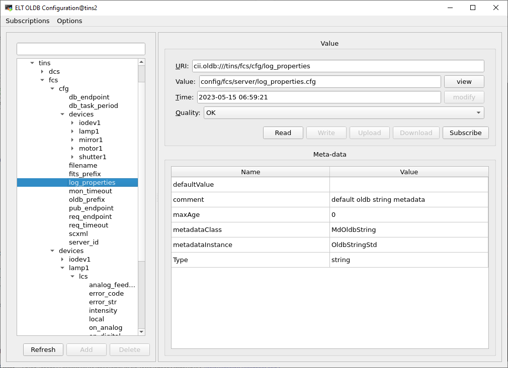
oldbGui utility
Server configuration
The server stores the actual values of the server configuration parameters into the OLDB . This helps to verify whether the configuration has been loaded correctly. For details of the server configuration parameters, see CII Configuration Service (config-ng).
OLDB Key |
|---|
elt/<instrument id>/<server id>/cfg/db_endpoint |
elt/<instrument id>/<server id>/cfg/db_timeout |
elt/<instrument id>/<server id>/cfg/dictionaries |
elt/<instrument id>/<server id>/cfg/filename |
elt/<instrument id>/<server id>/cfg/fits_prefix |
elt/<instrument id>/<server id>/cfg/log_properties |
elt/<instrument id>/<server id>/cfg/mon_timeout |
elt/<instrument id>/<server id>/cfg/oldb_prefix |
elt/<instrument id>/<server id>/cfg/pub_endpoint |
elt/<instrument id>/<server id>/cfg/req_endpoint |
elt/<instrument id>/<server id>/cfg/scxml |
elt/<instrument id>/<server id>/cfg/server_id |
Server Status
The server stores the string representation of its state and substate into the Redis DB.
OLDB Key |
|---|
elt/<instrument id>/<server id>/states/state |
elt/<instrument id>/<server id>/states/substate |
Common Device Keys
Each device has a number of common OLDB keys.
OLDB Key |
|---|
elt/<instrument id>/<server id>/cfg/devices/<device id>/dev_endpoint |
elt/<instrument id>/<server id>/cfg/devices/<device id>/sim_endpoint |
elt/<instrument id>/<server id>/cfg/devices/<device id>/cfgfile |
elt/<instrument id>/<server id>/cfg/devices/<device id>/fits_prefix |
elt/<instrument id>/<server id>/cfg/devices/<device id>/ignored |
elt/<instrument id>/<server id>/cfg/devices/<device id>/simulated |
elt/<instrument id>/<server id>/cfg/devices/<device id>/namespace |
elt/<instrument id>/<server id>/cfg/devices/<device id>/prefix |
elt/<instrument id>/<server id>/cfg/devices/<device id>/type |
Shutter
Each shutter device defines a set of specific OLDB keys:
OLDB Key |
|---|
elt/<instrument id>/<server id>/cfg/devices/<device id>/lcs/ignore_closed |
elt/<instrument id>/<server id>/cfg/devices/<device id>/lcs/ignore_fault |
elt/<instrument id>/<server id>/cfg/devices/<device id>/lcs/ignore_open |
elt/<instrument id>/<server id>/cfg/devices/<device id>/lcs/initial_state |
elt/<instrument id>/<server id>/cfg/devices/<device id>/lcs/low_closed |
elt/<instrument id>/<server id>/cfg/devices/<device id>/lcs/low_fault |
elt/<instrument id>/<server id>/cfg/devices/<device id>/lcs/low_open |
elt/<instrument id>/<server id>/cfg/devices/<device id>/lcs/low_switch |
elt/<instrument id>/<server id>/cfg/devices/<device id>/lcs/timeout |
elt/<instrument id>/<server id>/devices/<device id>/lcs/stat/error_code |
elt/<instrument id>/<server id>/devices/<device id>/lcs/stat/error_str |
elt/<instrument id>/<server id>/devices/<device id>/lcs/stat/local |
elt/<instrument id>/<server id>/devices/<device id>/lcs/stat/state |
elt/<instrument id>/<server id>/devices/<device id>/lcs/stat/substate |
Lamp
Each lamp device defines a set of specific OLDB keys:
OLDB key |
|---|
elt/<instrument id>/<server id>/cfg/devices/<device id>/lcs/analog_range |
elt/<instrument id>/<server id>/cfg/devices/<device id>/lcs/analog_threshold |
elt/<instrument id>/<server id>/cfg/devices/<device id>/lcs/cooldown |
elt/<instrument id>/<server id>/cfg/devices/<device id>/lcs/ignore_fault |
elt/<instrument id>/<server id>/cfg/devices/<device id>/lcs/initial_state |
elt/<instrument id>/<server id>/cfg/devices/<device id>/lcs/invert_analog |
elt/<instrument id>/<server id>/cfg/devices/<device id>/lcs/low_fault |
elt/<instrument id>/<server id>/cfg/devices/<device id>/lcs/low_on |
elt/<instrument id>/<server id>/cfg/devices/<device id>/lcs/low_switch |
elt/<instrument id>/<server id>/cfg/devices/<device id>/lcs/maxon |
elt/<instrument id>/<server id>/cfg/devices/<device id>/lcs/timeout |
elt/<instrument id>/<server id>/cfg/devices/<device id>/lcs/warmup |
elt/<instrument id>/<server id>/devices/<device id>/lcs/stat/error_code |
elt/<instrument id>/<server id>/devices/<device id>/lcs/stat/error_str |
elt/<instrument id>/<server id>/devices/<device id>/lcs/stat/intensity |
elt/<instrument id>/<server id>/devices/<device id>/lcs/stat/local |
elt/<instrument id>/<server id>/devices/<device id>/lcs/stat/state |
elt/<instrument id>/<server id>/devices/<device id>/lcs/stat/substate |
IODev
Each iodev device defines a set of specific OLDB keys:
OLDB key |
|---|
elt/<instrument id>/<server id>/cfg/devices/<device id>/<channel id>/description |
elt/<instrument id>/<server id>/cfg/devices/<device id>/<channel id>/fits_prefix |
elt/<instrument id>/<server id>/cfg/devices/<device id>/<channel id>/header |
elt/<instrument id>/<server id>/cfg/devices/<device id>/<channel id>/log |
elt/<instrument id>/<server id>/cfg/devices/<device id>/<channel id>/map |
elt/<instrument id>/<server id>/cfg/devices/<device id>/<channel id>/type |
elt/<instrument id>/<server id>/cfg/devices/<device id>/<channel id>/unit |
elt/<instrument id>/<server id>/devices/<device id>/lcs/stat/<channel id> |
elt/<instrument id>/<server id>/devices/<device id>/lcs/stat/state |
elt/<instrument id>/<server id>/devices/<device id>/lcs/stat/substate |
Psu8600
The psu8600 device defines the same set of OLDB keys as the iodev device.
Motor
Each motor device defines a set of specific OLDB keys:
OLDB key |
|---|
elt/<instrument id>/<server id>/cfg/devices/<device id>/lcs/active_low_indec |
elt/<instrument id>/<server id>/cfg/devices/<device id>/lcs/active_low_lhw |
elt/<instrument id>/<server id>/cfg/devices/<device id>/lcs/active_low_lstop |
elt/<instrument id>/<server id>/cfg/devices/<device id>/lcs/active_low_ref |
elt/<instrument id>/<server id>/cfg/devices/<device id>/lcs/active_low_uhw |
elt/<instrument id>/<server id>/cfg/devices/<device id>/lcs/active_low_ustop |
elt/<instrument id>/<server id>/cfg/devices/<device id>/lcs/axis_type |
elt/<instrument id>/<server id>/cfg/devices/<device id>/lcs/backlash |
elt/<instrument id>/<server id>/cfg/devices/<device id>/lcs/brake |
elt/<instrument id>/<server id>/cfg/devices/<device id>/lcs/check_inpos |
elt/<instrument id>/<server id>/cfg/devices/<device id>/lcs/disable |
elt/<instrument id>/<server id>/cfg/devices/<device id>/lcs/exec_post_init |
elt/<instrument id>/<server id>/cfg/devices/<device id>/lcs/exec_post_move |
elt/<instrument id>/<server id>/cfg/devices/<device id>/lcs/exec_pre_init |
elt/<instrument id>/<server id>/cfg/devices/<device id>/lcs/exec_pre_move |
elt/<instrument id>/<server id>/cfg/devices/<device id>/lcs/init_seq<number>_action |
elt/<instrument id>/<server id>/cfg/devices/<device id>/lcs/init_seq<number>_value1 |
elt/<instrument id>/<server id>/cfg/devices/<device id>/lcs/init_seq<number>_value2 |
elt/<instrument id>/<server id>/cfg/devices/<device id>/lcs/lock |
elt/<instrument id>/<server id>/cfg/devices/<device id>/lcs/lock_pos |
elt/<instrument id>/<server id>/cfg/devices/<device id>/lcs/lock_tolerance |
elt/<instrument id>/<server id>/cfg/devices/<device id>/lcs/low_brake |
elt/<instrument id>/<server id>/cfg/devices/<device id>/lcs/low_inpos |
elt/<instrument id>/<server id>/cfg/devices/<device id>/lcs/max_pos |
elt/<instrument id>/<server id>/cfg/devices/<device id>/lcs/min_pos |
elt/<instrument id>/<server id>/cfg/devices/<device id>/lcs/tout_init |
elt/<instrument id>/<server id>/cfg/devices/<device id>/lcs/tout_move |
elt/<instrument id>/<server id>/cfg/devices/<device id>/lcs/tout_switch |
elt/<instrument id>/<server id>/cfg/devices/<device id>/lcs/velocity |
elt/<instrument id>/<server id>/devices/<device id>/lcs/stat/axis_brake |
elt/<instrument id>/<server id>/devices/<device id>/lcs/stat/axis_enable |
elt/<instrument id>/<server id>/devices/<device id>/lcs/stat/axis_info_data1 |
elt/<instrument id>/<server id>/devices/<device id>/lcs/stat/inposition |
elt/<instrument id>/<server id>/devices/<device id>/lcs/stat/lock |
elt/<instrument id>/<server id>/devices/<device id>/lcs/stat/ready |
elt/<instrument id>/<server id>/devices/<device id>/lcs/stat/error_code |
elt/<instrument id>/<server id>/devices/<device id>/lcs/stat/error_str |
elt/<instrument id>/<server id>/devices/<device id>/lcs/stat/init_action |
elt/<instrument id>/<server id>/devices/<device id>/lcs/stat/init_step |
elt/<instrument id>/<server id>/devices/<device id>/lcs/stat/initialised |
elt/<instrument id>/<server id>/devices/<device id>/lcs/stat/local |
elt/<instrument id>/<server id>/devices/<device id>/lcs/stat/mode |
elt/<instrument id>/<server id>/devices/<device id>/lcs/stat/pos_actual |
elt/<instrument id>/<server id>/devices/<device id>/lcs/stat/pos_error |
elt/<instrument id>/<server id>/devices/<device id>/lcs/stat/pos_target |
elt/<instrument id>/<server id>/devices/<device id>/lcs/stat/scale_factor |
elt/<instrument id>/<server id>/devices/<device id>/lcs/stat/signal_index |
elt/<instrument id>/<server id>/devices/<device id>/lcs/stat/signal_lhw |
elt/<instrument id>/<server id>/devices/<device id>/lcs/stat/signal_lstop |
elt/<instrument id>/<server id>/devices/<device id>/lcs/stat/signal_ref |
elt/<instrument id>/<server id>/devices/<device id>/lcs/stat/signal_uhw |
elt/<instrument id>/<server id>/devices/<device id>/lcs/stat/signal_ustop |
elt/<instrument id>/<server id>/devices/<device id>/lcs/stat/state |
elt/<instrument id>/<server id>/devices/<device id>/lcs/stat/substate |
elt/<instrument id>/<server id>/devices/<device id>/lcs/stat/vel_actual |
elt/<instrument id>/<server id>/devices/<device id>/pos_actual_name |
elt/<instrument id>/<server id>/devices/<device id>/pos_enc |
elt/<instrument id>/<server id>/devices/<device id>/target_enc |
Derotator
The Derotator device uses the same set of OLDB keys as the Motor device plus some additional derotator specific ones that are described below:
OLDB key |
|---|
elt/<instrument id>/<server id>/cfg/devices/<device id>/lcs/trk_period |
elt/<instrument id>/<server id>/cfg/devices/<device id>/lcs/user_par1 |
elt/<instrument id>/<server id>/cfg/devices/<device id>/lcs/user_par2 |
elt/<instrument id>/<server id>/cfg/devices/<device id>/lcs/user_par3 |
elt/<instrument id>/<server id>/cfg/devices/<device id>/lcs/user_par4 |
elt/<instrument id>/<server id>/cfg/devices/<device id>/lcs/user_ref |
elt/<instrument id>/<server id>/cfg/devices/<device id>/lcs/sky_ref |
elt/<instrument id>/<server id>/cfg/devices/<device id>/lcs/tat_ref |
elt/<instrument id>/<server id>/devices/<device id>/lcs/stat/angle_on_sky |
elt/<instrument id>/<server id>/devices/<device id>/lcs/stat/alpha |
elt/<instrument id>/<server id>/devices/<device id>/lcs/stat/delta |
elt/<instrument id>/<server id>/devices/<device id>/lcs/stat/track_mode |
ADC
The Adc device defines a set of specific OLDB keys:
OLDB key |
|---|
elt/<instrument id>/<server id>/cfg/devices/<device id>/lcs/trk_period |
elt/<instrument id>/<server id>/cfg/devices/<device id>/lcs/afactor |
elt/<instrument id>/<server id>/cfg/devices/<device id>/lcs/minelev |
elt/<instrument id>/<server id>/cfg/devices/<device id>/lcs/poffset |
elt/<instrument id>/<server id>/cfg/devices/<device id>/lcs/pslope |
elt/<instrument id>/<server id>/cfg/devices/<device id>/lcs/toffset |
elt/<instrument id>/<server id>/cfg/devices/<device id>/lcs/tslope |
elt/<instrument id>/<server id>/cfg/devices/<device id>/lcs/zdlimit |
elt/<instrument id>/<server id>/cfg/devices/<device id>/lcs/mot1_coffset |
elt/<instrument id>/<server id>/cfg/devices/<device id>/lcs/mot1_drotfactor |
elt/<instrument id>/<server id>/cfg/devices/<device id>/lcs/mot1_poffset |
elt/<instrument id>/<server id>/cfg/devices/<device id>/lcs/mot1_refauto |
elt/<instrument id>/<server id>/cfg/devices/<device id>/lcs/mot1_refoff |
elt/<instrument id>/<server id>/cfg/devices/<device id>/lcs/mot2_coffset |
elt/<instrument id>/<server id>/cfg/devices/<device id>/lcs/mot2_drotfactor |
elt/<instrument id>/<server id>/cfg/devices/<device id>/lcs/mot2_poffset |
elt/<instrument id>/<server id>/cfg/devices/<device id>/lcs/mot2_refauto |
elt/<instrument id>/<server id>/cfg/devices/<device id>/lcs/mot2_refoff |
elt/<instrument id>/<server id>/cfg/devices/<device id>/ignored |
elt/<instrument id>/<server id>/cfg/devices/<device id>/simulated |
elt/<instrument id>/<server id>/devices/<device id>/lcs/stat/alpha |
elt/<instrument id>/<server id>/devices/<device id>/lcs/stat/delta |
elt/<instrument id>/<server id>/devices/<device id>/lcs/stat/error_code |
elt/<instrument id>/<server id>/devices/<device id>/lcs/stat/error_str |
elt/<instrument id>/<server id>/devices/<device id>/lcs/stat/local |
elt/<instrument id>/<server id>/devices/<device id>/lcs/stat/state |
elt/<instrument id>/<server id>/devices/<device id>/lcs/stat/substate |
elt/<instrument id>/<server id>/devices/<device id>/lcs/stat/track_mode |
elt/<instrument id>/<server id>/devices/<device id>/lcs/stat/motor1.axis_brake |
elt/<instrument id>/<server id>/devices/<device id>/lcs/stat/motor1.axis_enable |
elt/<instrument id>/<server id>/devices/<device id>/lcs/stat/motor1.axis_lock |
elt/<instrument id>/<server id>/devices/<device id>/lcs/stat/motor1.local |
elt/<instrument id>/<server id>/devices/<device id>/lcs/stat/motor1.pos_actual |
elt/<instrument id>/<server id>/devices/<device id>/lcs/stat/motor1.pos_enc |
elt/<instrument id>/<server id>/devices/<device id>/lcs/stat/motor1.scale_factor |
elt/<instrument id>/<server id>/devices/<device id>/lcs/stat/motor2.axis_brake |
elt/<instrument id>/<server id>/devices/<device id>/lcs/stat/motor2.axis_enable |
elt/<instrument id>/<server id>/devices/<device id>/lcs/stat/motor2.axis_lock |
elt/<instrument id>/<server id>/devices/<device id>/lcs/stat/motor2.local |
elt/<instrument id>/<server id>/devices/<device id>/lcs/stat/motor2.pos_actual |
elt/<instrument id>/<server id>/devices/<device id>/lcs/stat/motor2.pos_enc |
elt/<instrument id>/<server id>/devices/<device id>/lcs/stat/motor2.scale_factor |
elt/<instrument id>/<server id>/devices/<device id>/motor1.pos_enc |
elt/<instrument id>/<server id>/devices/<device id>/motor2.pos_enc |
Piezo
The Piezo device defines a set of specific OLDB keys:
OLDB key |
|---|
elt/<instrument id>/<server id>/cfg/devices/<device id>/lcs/home1 |
elt/<instrument id>/<server id>/cfg/devices/<device id>/lcs/home2 |
elt/<instrument id>/<server id>/cfg/devices/<device id>/lcs/home3 |
elt/<instrument id>/<server id>/cfg/devices/<device id>/lcs/lower_limit1 |
elt/<instrument id>/<server id>/cfg/devices/<device id>/lcs/lower_limit2 |
elt/<instrument id>/<server id>/cfg/devices/<device id>/lcs/lower_limit3 |
elt/<instrument id>/<server id>/cfg/devices/<device id>/lcs/upper_limit1 |
elt/<instrument id>/<server id>/cfg/devices/<device id>/lcs/upper_limit2 |
elt/<instrument id>/<server id>/cfg/devices/<device id>/lcs/upper_limit3 |
elt/<instrument id>/<server id>/cfg/devices/<device id>/lcs/max_on |
elt/<instrument id>/<server id>/cfg/devices/<device id>/lcs/num_axes |
elt/<instrument id>/<server id>/cfg/devices/<device id>/lcs/user_offset_input1 |
elt/<instrument id>/<server id>/cfg/devices/<device id>/lcs/user_offset_input2 |
elt/<instrument id>/<server id>/cfg/devices/<device id>/lcs/user_offset_input3 |
elt/<instrument id>/<server id>/cfg/devices/<device id>/lcs/user_to_bit_input1 |
elt/<instrument id>/<server id>/cfg/devices/<device id>/lcs/user_to_bit_input2 |
elt/<instrument id>/<server id>/cfg/devices/<device id>/lcs/user_to_bit_input3 |
elt/<instrument id>/<server id>/cfg/devices/<device id>/lcs/user_offset_output1 |
elt/<instrument id>/<server id>/cfg/devices/<device id>/lcs/user_offset_output2 |
elt/<instrument id>/<server id>/cfg/devices/<device id>/lcs/user_offset_output3 |
elt/<instrument id>/<server id>/cfg/devices/<device id>/lcs/user_to_bit_output1 |
elt/<instrument id>/<server id>/cfg/devices/<device id>/lcs/user_to_bit_output2 |
elt/<instrument id>/<server id>/cfg/devices/<device id>/lcs/user_to_bit_output3 |
elt/<instrument id>/<server id>/devices/<device id>/lcs/stat/actual_pos_bit1 |
elt/<instrument id>/<server id>/devices/<device id>/lcs/stat/actual_pos_bit2 |
elt/<instrument id>/<server id>/devices/<device id>/lcs/stat/actual_pos_bit3 |
elt/<instrument id>/<server id>/devices/<device id>/lcs/stat/actual_pos_user1 |
elt/<instrument id>/<server id>/devices/<device id>/lcs/stat/actual_pos_user2 |
elt/<instrument id>/<server id>/devices/<device id>/lcs/stat/actual_pos_user3 |
elt/<instrument id>/<server id>/devices/<device id>/lcs/stat/error_codes |
elt/<instrument id>/<server id>/devices/<device id>/lcs/stat/error_str |
elt/<instrument id>/<server id>/devices/<device id>/lcs/stat/local |
elt/<instrument id>/<server id>/devices/<device id>/lcs/stat/state |
elt/<instrument id>/<server id>/devices/<device id>/lcs/stat/substate |
Actuator
Each actuator device defines a set of specific OLDB keys:
OLDB key |
|---|
elt/<instrument id>/<server id>/devices/<device id>/lcs/stat/local |
elt/<instrument id>/<server id>/devices/<device id>/lcs/stat/state |
elt/<instrument id>/<server id>/devices/<device id>/lcs/stat/substate |
elt/<instrument id>/<server id>/devices/<device id>/lcs/stat/error_code |
elt/<instrument id>/<server id>/devices/<device id>/lcs/stat/error_str |
Command Interface
The commands currently supported by the server are listed here: Client Application.
Error Handling
FCF Commands throw exceptions in case of errors or timeouts. Client applications can catch the exceptions and obtain the error message associated with the function getDesc(). This error does not contain neither the history nor the error stack but it normally indicates precisely where the error occurred.
try {
    auto reply = client->GetStatus();
 } catch (const fcfif::ExceptionErr& e) {
    RAD_LOG_ERROR() << "Error reply " << e.getDesc()  << ").";
}
Serialization
The Device Manager uses the CII MAL ZPB (ZeroMQ + Google Proto buffers) for serialising commands.
Note
Each command has two parts: a payload and its corresponding reply, see the details in the fcfif module. The normal replies are plain strings.
Setup Command
The Setup command is intended to produce a change in the run-time configuration. It is also a way of triggering operational actions on the devices. It is possible to switch a lamp on, close a shutter and move a motor in separate messages or within the same one. This means that the content of the message varies. The devices will de-serialise the message and communicate the actions to be taken to the corresponding PLCs via the interface with the LCS.
The DevMgr is not blocked when receiving concurrent Setup commands (messages). It executes them in separate worker threads that are spawned per each new Setup command. The threads will be running until the commands have been executed successfully, an error occured, the timeout has elapsed or a Stop command is received, see figure below.
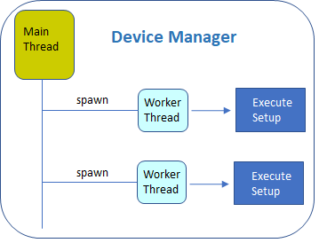
Device Manager Setup worker threads.
Note
A Stop command finalizes all ongoing worker threads that are being handled by the Device Manager.
Warning
Conflicting requests across different Setup commands running in parallel are not handled by the Device Manager. They are pushed down to the PLC. The PLC is resolving them depending on the actual status. This means that, if the user sends two consecutive commands with conflicting requests, most likely the second one will get an error from the PLC. The exact behaviour will depend on the specific Device Controller implementation.
Setup Interface Definition
The interface definition of the Setup command can be found in module fcfif. The payload is based on an array of unions. The union may contain any device supported by the Device Manager.
<union name="DeviceUnion">
    <discriminator type="nonBasic" nonBasicTypeName="DeviceType" />
    <case>
        <caseDiscriminator value ="SHUTTER"/>
            <member name="shutter" type="nonBasic" nonBasicTypeName="ShutterDevice" />
    </case>
    <case>
        <caseDiscriminator value ="LAMP"/>
            <member name="lamp" type="nonBasic" nonBasicTypeName="LampDevice" />
    </case>
    <case>
    <caseDiscriminator value ="MOTOR"/>
            <member name="motor" type="nonBasic" nonBasicTypeName="MotorDevice" />
    </case>
    <case>
    <caseDiscriminator value ="DROT"/>
            <member name="drot" type="nonBasic" nonBasicTypeName="DrotDevice" />
    </case>
    <case>
    <caseDiscriminator value ="ADC"/>
            <member name="adc" type="nonBasic" nonBasicTypeName="AdcDevice" />
    </case>
    <case>
    <caseDiscriminator value ="PIEZO"/>
            <member name="piezo" type="nonBasic" nonBasicTypeName="PiezoDevice" />
    </case>
    <case>
    <caseDiscriminator value ="ACTUATOR"/>
            <member name="actuator" type="nonBasic" nonBasicTypeName="ActuatorDevice" />
    </case>
    <case>
    <caseDiscriminator value ="MAXIS"/>
            <member name="maxis" type="nonBasic" nonBasicTypeName="ActuatorDevice" />
    </case>
    <case>
    <caseDiscriminator value ="MATRK"/>
            <member name="matrk" type="nonBasic" nonBasicTypeName="ActuatorDevice" />
    </case>
    <case>
    <caseDiscriminator value ="IODEV"/>
            <member name="iodev" type="nonBasic" nonBasicTypeName="IODevDevice" />
    </case>
    <case>
    <caseDiscriminator value ="CUSTOM"/>
            <member name="custom" type="nonBasic" nonBasicTypeName="CustomDevice" />
    </case>
</union>
Warning
The array does not have a fixed size but it has a limit of 100 elements. A limit is needed by the CII XML ICD.
<method name="Setup" returnType="string" throws="ExceptionErr">
    <argument name="payload" type="nonBasic" nonBasicTypeName="SetupElem" arrayDimensions="(100)"/>
</method>
Each device structure may contain parameters and one action per device that can be serialized. An example of the device ICD is shown below.
<struct name="ShutterDevice">
    <member name="id" type="string" />
    <member name="action" type="nonBasic" nonBasicTypeName="ActionShutter" />
</struct>

<struct name="LampDevice">
    <member name="id" type="string" />
    <member name="intensity" type="double" />
    <member name="time" type="uint32_t" />
    <member name="action" type="nonBasic" nonBasicTypeName="ActionLamp" />
</struct>

<struct name="BaseMotorDevice">
   <member name="id" type="string" />
    <member name="name" type="string" />
    <member name="pos" type="double" />
    <member name="enc" type="int64_t" />
    <member name="speed" type="double" />
    <member name="unit" type="nonBasic" nonBasicTypeName="MotorPosUnit" />
</struct>

<struct name="MotorDevice" baseType="BaseMotor">
    <member name="action" type="nonBasic" nonBasicTypeName="ActionMotor" />
</struct>

<struct name="DrotDevice" baseType="BaseMotor">
    <member name="mode" type="nonBasic" nonBasicTypeName="ModeDrot" />
    <member name="action" type="nonBasic" nonBasicTypeName="ActionDrot" />
</struct>

<struct name="AdcDevice" baseType="BaseMotor">
    <member name="axis" type="nonBasic" nonBasicTypeName="AxesAdc" />
    <member name="mode" type="nonBasic" nonBasicTypeName="ModeAdc" />
    <member name="action" type="nonBasic" nonBasicTypeName="ActionAdc" />
</struct>

<struct name="PiezoDevice">
    <member name="id" type="string" />
    <member name="bit1" type="uint32_t" />
    <member name="bit2" type="uint32_t" />
    <member name="bit3" type="uint32_t" />
    <member name="pos1" type="double" />
    <member name="pos2" type="double" />
    <member name="pos3" type="double" />
    <member name="action" type="nonBasic" nonBasicTypeName="ActionPiezo" />
</struct>

<struct name="ActuatorDevice">
    <member name="id" type="string" />
    <member name="action" type="nonBasic" nonBasicTypeName="ActionActuator" />
</struct>

<struct name="IODevDevice">
    <member name="digarray" type="nonBasic" nonBasicTypeName="DigitalElem" arrayDimensions="(30)" />
    <member name="anlgarray" type="nonBasic" nonBasicTypeName="AnalogElem" arrayDimensions="(30)" />
    <member name="intarray" type="nonBasic" nonBasicTypeName="IntegerElem" arrayDimensions="(30)" />
    <member name="action" type="nonBasic" nonBasicTypeName="ActionIODev" />
</struct>

<struct name="MAxisDevice">
    <member name="action" type="nonBasic" nonBasicTypeName="ActionMAxis" />
    <member name="name" type="string" />
    <member name="axes" type="nonBasic" nonBasicTypeName="AxisSetup" arrayDimensions="(6)"/>
    <member name="custom" type="string" />
</struct>

<struct name="MAtrkDevice">
    <member name="action" type="nonBasic" nonBasicTypeName="ActionMAtrk" />
    <member name="axes" type="nonBasic" nonBasicTypeName="AxisSetup" arrayDimensions="(6)"/>
    <member name="mode" type="string" />
    <member name="pos" type="double" />
    <member name="name" type="string" />
    <member name="unit" type="nonBasic" nonBasicTypeName="MotorPosUnit" />
    <member name="offset" type="double" />
    <member name="custom" type="string" />
</struct>
<struct name="CustomDevice">
    <member name="parameters" type="string" />
</struct>
Note
The CustomDevice is to be used for implementing custom devices where the payload data can be
serialized in JSON. The serialization shall be done by the client applications using the parameters
in the CustomDevice structure to carry the information encoded in JSON. The above enables extendability
without the need to provide specific CII XML ICDs which is a significant simplification for instruments.
Note
The examples of the commands are using the FCF shell described in the Client section. For details of the FCF client shell, see Client Application. Since shell commands match python methods, they do not follow the Device Manager command names.
DevStatus Command
The DevStatus command provides information about each device controlled by the Device Manager. An example of the output generated by the DevStatus command is shown below.
$ fcfSh> devstatus_regex

shutter1.simulated = true
shutter1.lcs.state = Operational
shutter1.lcs.substate = Close
lamp1.simulated = true
lamp1.lcs.state = Operational
lamp1.lcs.substate = Off
lamp1.lcs.intensity = 0.000000
motor1.simulated = true
motor1.lcs.state = Operational
motor1.lcs.substate = Standstill
motor1.lcs.pos_target = 30.000000
motor1.lcs.pos_actual = 30.002197
motor1.lcs.vel_actual = 0.000000
motor1.lcs.axis_enable = true
motor1.pos_actual_name = ON
motor1.pos_enc = 341
The user could request the status of a specific device or a subset of the devices, see below.
$ fcfSh> devstatus_regex motor1
motor1.simulated = true
motor1.lcs.state = Operational
motor1.lcs.substate = Standstill
motor1.lcs.pos_target = 30.000000
motor1.lcs.pos_actual = 30.002197
motor1.lcs.vel_actual = 0.000000
motor1.lcs.axis_enable = true
motor1.pos_actual_name = ON
motor1.pos_enc = 341


$ fcfSh> devstatus_regex lamp1
lamp1.simulated = true
lamp1.lcs.state = Operational
lamp1.lcs.substate = Off
lamp1.lcs.intensity = 0.000000
Note
The list of devices is comma-separated.
Ignore Command
This command tells the Device Manager to completely ignore a device. It can be used when there are hardware failures or when the hardware is not yet available. The following example shows a sequence that ignores device lamp1, gets the status of the devices and then stops ignoring the device.
Note
When a device is ignored, no other information is provided for this device when processing the status command.
$ fcfSh> ignore lamp1
$ fcfSh> devstatus_regex lamp1
lamp1.ignored = true

$ fcfSh> stop_ignore lamp1
$ fcfSh> devstatus_regex lamp1
lamp1.simulated = true
lamp1.lcs.state = Operational
lamp1.lcs.substate = Off
lamp1.lcs.intensity = 0.000000
Simulate Command
This command tells the Device Manager to use the simulation address of the device. If the Device Manager is already connected, it will disconnect from the normal address and connect to the simulator. When the simulation is stopped, the server reverts the action and the device is back to normal mode.
The purpose of the simulation is to be able to validate the response of the Device Manager under different error conditions. It also allows to test the high-level SW when the HW is not yet available.
$ fcfSh> simulate lamp1
$ fcfSh> devstatus_regex lamp1
lamp1.simulated = true
lamp1.lcs.state = Operational
lamp1.lcs.substate = Off
lamp1.lcs.intensity = 0.000000

$ fcfSh> stop_simulate lamp1
$ fcfSh> devstatus_regex lamp1
lamp1.lcs.state = Operational
lamp1.lcs.substate = Off
lamp1.lcs.intensity = 0.000000
DevNames Command
The DevNames command provides the list of devices managed by the Device Manager.
DevsInfo Command
The DevsInfo command provides the list of devices managed by the Device Manager with their corresponding types.
DevConfig
The DevConfig command provides the loaded configuration of a particular device.
Device Specific Commands
Open
The Open command can be used to open a shutter device.
Close
The Close command can be used to close a shutter device.
SwitchOn
The SwitchOn command can be used to switch on a lamp or actuator device.
SwitchOff
The SwitchOff command can be used to switch off a lamp or actuator device.
MoveAbs
The MoveAbs command can be used to move a motor device in absolute position.
MoveByName
The MoveByName command can be used to move a motor device to a defined named position.
StartTrack
The StartTrack command can be used to the tracking for a derotator device.
StopTrack
The StopTrack command can be used to the tracking for a derotator device.
TrackOffset
The TrackOffset command can be used to issue an offset during tracking. Only for tracking devices.
FITS Header Information
The FCF FITS header is the composition of all the keywords provided by each device present in the server configuration.
Common Keywords
Keyword |
Type |
Description |
|---|---|---|
INS.<prefix>.DEVIGN |
Bool |
This keyword is present when the device is ignored. When this happens no other keywords are present. Having a device ignored is a degraded condition and should not happen in normal operations. |
INS.<prefix>.DEVSIM |
Bool |
This keyword is present when the device is simulated. |
INS.<prefix>.ID |
String |
This keyword contains the device ID. The information is taken from the device configuration (id). |
INS.<prefix>.NAME |
String |
This keyword contains the device name. The information is taken from the device configuration (alias). |
Lamp Specific Keywords
Keyword |
Type |
Description |
|---|---|---|
INS.<prefix>.STAT |
String |
This keyword contains the status of the device as string (On or Off). |
Actuator Specific Keywords
The specific keywords of the actuator device are the same as in the lamp.
Shutter Specific Keywords
Keyword |
Type |
Description |
|---|---|---|
INS.<prefix>.STAT |
String |
This keyword contains the status of the device as string (Open or Closed). |
Piezo Specific Keywords
Keyword |
Type |
Description |
|---|---|---|
INS.<prefix>.STAT |
String |
This keyword contains the operational status of the device as string (Open, Auto or Error). |
Motor Specific Keywords
Keyword |
Type |
Description |
|---|---|---|
INS.<prefix>.STAT |
String |
This keyword contains the operational status of the device as string (Standstill, Moving or Error). |
INS.<prefix>.ID |
String |
In case of a motor device, the ID represents the device id as for all devices or the id of the position when using named positions. |
INS.<prefix>.NAME |
String |
In case of a motor device, the NAME represents the device alias as for all devices or the name of the position when using named positions. |
INS.<prefix>.TYPE |
String |
This keyword is present only when using named positions. It contains the type of the specific position selected, e.g. MASK. Types for each position are defined in the configuration of the device. |
INS.<prefix>.NO |
String |
This keyword is present only when using named positions. It contains the slot of the specific position selected. Slots for each position are defined in the configuration of the device. |
Derotator Specific Keywords
Keyword |
Type |
Description |
|---|---|---|
INS.<prefix>.STAT |
String |
This keyword contains the operational status of the device as string (Standstill, Moving or Error). |
INS.<prefix>.MODE |
String |
This keyword contains the mode of the device as string (Stat, Sky, Elev or User). |
INS.<prefix>.ROTATION |
String |
This keyword is present only when device is tracking. It contains the value of the rotation as obtained from the telescope. |
INS.<prefix>.PUPIL |
String |
This keyword is present only when device is tracking. It contains the value of the pupil as obtained from the telescope. |
INS.<prefix>.POSANG |
String |
This keyword is present only when device is tracking. It contains the value of the position angle. |
ADC Specific Keywords
Keyword |
Type |
Description |
|---|---|---|
INS.<prefix>.STAT |
String |
This keyword contains the operational status of the device as string (Standstill, Moving, Tracking or Error). |
IODev Specific Keywords
Keyword |
Type |
Description |
|---|---|---|
INS.<prefix>.<channel>.<channel prefix> |
Double|Integer|String |
This keyword contains the value of the channel sensor. It will be replicated as many times as channels defined in the device. |
Troubleshooting
Logging
The Device Manager has implemented logging based on the log4cplus package. The log4cplus package defines four standard logging levels that could give additional information to the developer for troubleshooting.
Name |
Verbosity |
Description |
|---|---|---|
ERROR |
very low |
Provide logging only in case of errors (default). |
INFO |
low |
Provide information for the most important actions. |
DEBUG |
medium |
Provide additional information for the developer. |
TRACE |
very high |
Includes all the function tracing. |
To activate a new logging, the command SetLogLevel shall be used. See the example below.
$ fcfcli --uri zpb.rr://127.0.0.1:12083
$ fcfSh> setloglevel TRACE
Note
This logging level affects only the general Devmgr logger.
Loggers
The Devmgr provides a default configuration (log_cii_properties.cfg) for the logging for CII logging service.
This configuration defines one general logger (app) and a logger per device type, e.g. (shutter).
The device loggers will help when troubleshooting specific devices.
Logger |
Description |
|---|---|
app |
General logger for common server classes. |
shutter |
Specific logger for Shutter classes. |
lamp |
Specific logger for lamp classes. |
motor |
Specific logger for motor classes. |
sensor |
Specific logger for sensor classes. |
piezo |
Specific logger for piezo classes. |
actuator |
Specific logger for actuator classes. |
iodev |
Specific logger for iodev classes. |
drot |
Specific logger for drot classes. |
adc |
Specific logger for adc classes. |
To activate a new logging level for a specific logger, one should use the FCF CLI, see the example below.
$ fcfcli --uri zpb.rr://127.0.0.1:12083
$ fcsSh> setloglevel TRACE,lamp
The server will start logging the tracing information for the lamp classes and you should see something like the following:
2021-07-02T14:30:17.624 TRACE ENTER: virtual void fcf::devmgr::lamp::Lamp::Setup(const std::any&)
2021-07-02T14:30:17.624 TRACE EXIT:  virtual void fcf::devmgr::lamp::Lamp::Setup(const std::any&)
2021-07-02T14:30:17.638 TRACE ENTER: virtual bool fcf::devmgr::lamp::Lamp::IsSetupActive(const std::any&) const
2021-07-02T14:30:17.638 TRACE EXIT:  virtual bool fcf::devmgr::lamp::Lamp::IsSetupActive(const std::any&) const
...
Note
If a the second parameter is not provided, the logging level will affect the general logger.
Note
If you are missing some logging information for some devices, it might be that the logging is happening in the specific device classes so you need to enable the device logger to see all the logging. When you use the application logger, it affects only to the common classes.
Log File
The default log configuration provides two appenders. One for the console and another one for a file. The file is stored in the CII Logging directory (CII_LOGS). The name of the file is fcfDevmgr.log.
Logging Viewer
Since version 5.0.0, the logs can be visualised using the CII Logging Viewer.
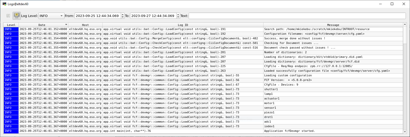
CII Viewer Console.
OPC-UA Client
Sometimes it is better to check the status of the PLC using an OPC-UA client. One of the best tools available is the UaExpert from Unified Automation. This tool enables the control and monitoring of all device variables independently of the Device Manager. The user can trigger the execution of RPCs and monitor the device state changes. The UaExpert is an essential tool for troubleshooting.
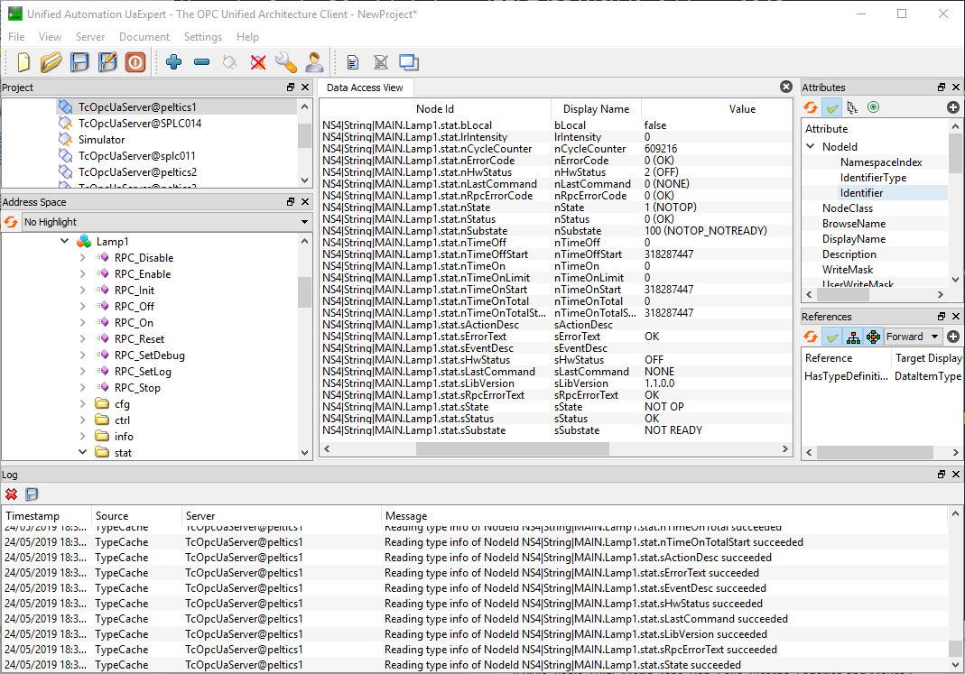
UaExpert OPC-UA client.