Introduction
Scope
This document is a configuration guide for Beckhoff PLCs used for ESO projects. It details how to order PLCs and corresponding licenses as well as how to configure PLCs before connecting them to the control network.
Definitions, Acronyms and Abbreviations
This document employs several abbreviations and acronyms to refer concisely to an item, after it has been introduced. The following list is aimed to help the reader in recalling the extended meaning of each short expression:
TBC |
To Be Clarified |
|---|---|
TBD |
To Be Defined |
PLC |
Programable Logic Controller |
TwinCAT |
The Windows Control and Automation Technology |
Buying a PLC
TwinCAT 3 Platform Level (performance level)
TwinCAT 3 Runtime components are available for different performance platforms (performance levels, platform levels). Performance levels currently range from 40 to 94. The TwinCAT 3 license price depends on the platform level and the level has to be specified in the license order number.
Examples of TwinCAT 3 platform levels are shown in Fig. 1.

Fig. 1 TC3 Performance Platforms (source: Beckhoff Info System)
Standard PLC
Currently, the standard PLC for ESO instruments is CX2030-0125 with 16 GB of CFast disk (CX2900-0033) instead of the default 8 GB disk. The performance level of this unit is 60. The option 0125 means that the system comes preinstalled with:
Windows Embedded Standard 7 P 32-bit OS and
TwinCAT3 Runtime (XAR).
The CX2030 also requires a Power Supply unit CX2100-0004.
PLC Licenses
Each PLC needs run-time licenses. The simplest way is to order licenses together with the PLC in the same purchase order. This way the PLC comes preconfigured by Beckhoff and the user doesn’t have to handle the licenses himself. If additional licenses are needed later on, they can be purchased and then activated by the user.
The following sections describe each item in a purchase order and then give an example of a complete purchase order that includes both HW and licenses.
PLC licenses are one-off licenses tied to the HW and the performance platform. Licenses bought for a certain performance platform can be used for that platform or a lower one but not for a higher platform. For example, licenses bought for CX2030 (60) could be used for CX5120 (40) but not for CX2040 (70).
For more information about TwinCAT licenses, go to Beckhoff Information System and search for Working with TwinCAT 3 license dongles.
Ordering Standard Licenses
TwinCAT 3 standard licenses are always linked to specific hardware. This is usually a TwinCAT 3 license dongle (EL6070 License Key Terminal or C9900-L100 license key USB stick). In principle it is also possible to tie a TwinCAT 3 license to a specific Beckhoff PLC, e.g. CX2030. However, this has a severe disadvantage that, if the PLC is replaced, the TwinCAT 3 licenses are no longer valid for the new PLC. If, on the other hand, the TwinCAT 3 licenses are tied to a TwinCAT 3 license dongle, the PLC can easily be replaced. In addition, spare PLCs that are kept in stock as replacement units don’t need additional licenses.

Fig. 2 License Dongles (source: Beckhoff Info System)
It is recommended to order licenses on the License terminal EL6070-0033.
It is also recommended that the EL6070 terminal is placed as the very first terminal after the CX2100-0004 Power Supply, so its presence is clear when replacing a broken PLC (see Fig. 3).

Fig. 3 Recommended Position for License Dongle EL6070
Mandatory Licenses
There are two runtime licenses that are mandatory for each PLC. One is needed for the PLC Runtime and the other one for the communication with the PLC. The designation pp in the license catalogue number stands for Performance Platform and is 60 for the standard CX2030. When ordering, pp should be substituted with the correct performance platform, e.g. 60.
License Order # |
Description |
Note |
|---|---|---|
TC1200-00pp |
TC3 PLC |
This is a license to run PLC programs |
TF6100-00pp |
TC3 OPC UA |
This is the license for the OPC UA, the standard communication interface between the PLC and the outside world. |
Additional Licenses
Depending on the PLC application, additional licenses might be needed. The most common licenses are for the motion control and for the communication via serial port or TCP/IP. We also use C++ for some code that has been ported from VxWorks systems.
License Order # |
Description |
Note |
|---|---|---|
TF5000-00pp |
TC3 NC PTP 10 Axes |
Motion control for up to 10 axes. |
TF5010-00pp |
TC3 NC PTP Axes Pack 25 |
Motion control for up to 25 axes. This license is in addition to TF5000-00pp! Essentially it adds 15 axes to the system. |
TC1300-00pp |
TC3 C++ |
Programming in C++ |
TF6311-00pp |
TC3 TCP/UDP Realtime |
TCP/UDP communication |
TF6340-00pp |
TC3 Serial Communication |
RS-232, 422 & 485 |
License Bundles
License bundles are just a simplified way of ordering licenses since one license catalogue number can contain two or more licenses. For example, TC1250-00pp (TC3 PLC/C++) contains both licenses TC1200-00pp and TC1300-00pp. From the cost point of view there is no advantage in ordering licenses in a bundle. The total cost of licenses is always the same regardless of if they were purchased in a bundle or individually.
Ordering TwinCAT 3 Standard Licenses with and without Pre-activation
To enable unambiguous assignment of TwinCAT 3 licenses for pre-activation and the required licensing platform (dongle or PLC) in the purchase order, please refer to Table 3 when ordering. The order number of the TwinCAT 3 license dongle indicates whether or not to pre-activate licenses for the dongle.
Order number |
Description |
|---|---|
EL6070-0033 or C9900-L100-0033 |
TwinCAT 3 dongle with pre-activated TwinCAT 3 licenses |
EL6070-0000 or C9900-L100-0000 |
Empty TwinCAT 3 dongle (without pre-activated TwinCAT 3 licenses) |
The order number of the TwinCAT 3 license is important for pre-activation of TwinCAT 3 licenses for a type …-0033 dongle. In this case, the third last digit of the TwinCAT 3 product number must be “1”. When reordering licenses for a TwinCAT 3 license dongle that is already with the customer, the license must be activated by the customer. In this case, the third last digit of the TwinCAT 3 product number must be “2”.
Examples of the two above cases are given in Table 4. License order is for performance platform 60, i.e. for CX2030.
License Order # |
Description |
|---|---|
TC1200-0160 |
Pre-activation by Beckhoff for a TwinCAT 3 license dongle in the same purchase order. |
TC1200-0260 |
No pre-activation by Beckhoff (license activation by customer) |
Quotation/Purchase Order Examples
In this section we provide examples of possible ways to order a PLC CX2030 including the licenses for PLC programming, OPC UA communication, up to 25 motor axes and the support for C++ programming. Note that the option given in Option with EL6070 License Terminal EL6070-0033 (recommended) is the recommended one.
Licenses Linked to the PLC (not recommended)
CX2030-0125 |
Industrial PC with pre-installed TwinCAT 3 Runtime |
CX2100-0004 |
Power supply for PC |
CX2900-0033 |
16 GB CFast card, instead of 8 GB CFast card |
TC1250-0060 |
TC3 PLC / NC PTP 10 |
TC1300-0060 |
TC3 C++ |
TF5010-0060 |
TC3 NC PTP Axes Pack 25 |
TF6100-0060 |
TC3 OPC UA |
Option with USB License dongle C9900-L100-0033
CX2030-0125 |
Industrial PC with pre-installed TwinCAT 3 Runtime |
CX2100-0004 |
Power supply for PC |
CX2900-0033 |
16 GB CFast card, instead of 8 GB CFast card |
C9900-L100-0033 |
License dongle with pre-activated TwinCAT 3 licenses |
TC1250-0160 |
TC3 PLC / NC PTP 10 |
TC1300-0160 |
TC3 C++ |
TF5010-0160 |
TC3 NC PTP Axes Pack 25 |
TF6100-0160 |
TC3 OPC UA |
Option with EL6070 License Terminal EL6070-0033 (recommended)
CX2030-0125 |
Industrial PC with pre-installed TwinCAT 3 Runtime |
CX2100-0004 |
Power supply for PC |
CX2900-0033 |
16 GB CFast card, instead of 8 GB CFast card |
EL6070-0033 |
License Key Terminal with pre-activated TwinCAT 3 licenses |
TC1250-0160 |
TC3 PLC / NC PTP 10 |
TC1300-0160 |
TC3 C++ |
TF5010-0160 |
TC3 NC PTP Axes Pack 25 |
TF6100-0160 |
TC3 OPC UA |
PLC Configuration
PLCs are normally placed on the control network. Therefore, they should be assigned a name and the IP address. The following sections describe how to configure a newly arrived PLC. Please note that ALL configuration steps are needed for correct configuration. Most of the configuration steps include a link to the corresponding videos of the procedure executions.
New PLCs arrive with factory preset names and IP addresses that do not match the control network. This makes it difficult to remotely connect to the PLC. The easiest way to start working with a new PLC is to connect a screen, a mouse and a keyboard directly to the PLC. This way the PLC is seen as any other Windows PC.
Backup of Delivered System
The first and very important step is to make a backup of the hard disk (CFast SSD) of the delivered system, just in case something goes wrong, and the user has to recover the system.
Backup can be done using freeware program Clonezilla. However, it is recommended to use Beckhoff Service Tool C9900-H377 that is based on Acronis and is delivered on a bootable USB stick. Around 5GB of storage is needed for the complete backup of the system. The USB stick has enough space for two or three PLC backups.
Insert the USB stick into one of the available USB ports on the PLC and reboot the PLC. Select Backup and follow the instructions. Once the backup is complete, transfer the backup (*.tib) file to a safe place on a PC.
Setting IP address
If possible, plug in one side of a network cable to the upper network port of the PLC and the other side to a PC or some network. This will help to easily identify the network connection in the Control Panel. The unused port should display “Network cable unplugged”. Normally, the upper connection has a name with higher number in it than the lower port, e.g. Local Area Connection 2.
The procedure is the following:
Go to: Start\Control Panel\Network and Sharing Center
Select: Change adapter settings
Right-click on the network to configure and select Properties.
Scroll down to Internet Protocol Version 4 (TCP/IPv4), click on it and then press the Properties button.
A dialog shown in Fig. 4 will pop up. Enter the required configuration and press OK.
A video showing how to set the IP address can be found here .

Fig. 4 Setting of IP Address
Changing PLC Name
The procedure is the following:
Go to: Start\Control Panel\System
Select: Change settings in the lower right side of the screen.
Under the Computer Name tab press the Change… button.
Enter the new name in the “Computer name” input field and confirm with OK.
Once the name has been changed, the PLC has to be rebooted for the change to take effect.
A video showing how to change the name of the PLC can be found here .
Enabling Firewall
Firewall for both network ports should be active, i.e. turned ON, as shown on Fig. 5.
The procedure is the following:
Go to: Start\Control Panel\Windows Firewall
Click on: Turn Windows Firewall on or off in the upper left side of the screen.
Turn on Windows Firewall for both networks and confirm with OK.

Fig. 5 Both Networks with Firewall ON
Opening OPC UA Port 4840
Due to the active firewall, in order to be able to communicate with the PLC from the high-level software, a special port 4840 will have to be open.
The port is open from the Control Panel Firewall Advanced settings by defining a new inbound rule.
A video showing how to open OPC UA port 4840 can be found here.
Enable ping Service
The ping service can be enabled from the Control Panel Firewall Advanced settings by reconfiguring one of the existing Inbound rules for File and Printer Sharing (Echo Request – ICMPv4-In) for Private, Public Profile. The Remote Address must be changed from Local subnet to Any.
A video showing how the ping service is enabled can be found here.
Note: From this point on, the PLC can be put on the network and accessed via Remote Desktop.
Install and Configure OPC UA Server v5
Since version 4.4.0, the TwinCAT OPC UA Server has added some complexity to the installation and initialization process to increase security. This chapter describes the entire process of installing a new Server version with the additional security but allowing the OPC UA Server to be back compatible with the less secure communication methods.
Install OPC UA Server v5 and OPC UA Configurator
Login to PLC using the Remote Desktop.
Double-click the downloaded binary for the OPC UA Server and start the installation process.
A popup will come up with an option of installing a none/none endpoint, this should be selected.

Fig. 6 . .
Complete the installation.
Double click the downloaded binary for the OPC UA Configurator and complete the installation.
Reboot the PLC.
Connecting for the First Time
Using UAExpert connect to the PLC using the Basic256Sha256 method and Anonymous user.

Fig. 7 . .
Ignore any error.
Temporarily accept the server certificate and press Continue.

Fig. 8 . .
Find the RPC call TrustOnFirstUse and call it by right-clicking on the name.

Fig. 9 . .
The values for Username: opcua_user and Password: pass4u! should be filled in. This user will be created as a Windows user and will become the administrator user for the OPC UA Server.

Fig. 10 . .
Press the Call button. The Result should be Succeeded, and the AddStatus value should be “0 (Succeeded)”. Then, after a couple of seconds, the OPC UA Server should reset.
If the AddStatus is not as expected (see example in Fig. 11), most likely the OPC UA Server and the Configurator will have to be uninstalled, and the user opcua_user deleted from the system, before the complete process is repeated. Chapter Uninstalling Existing OPC UA Server describes this procedure.

Fig. 11 . .
If there is a Connect Error, Ignore it to continue.
Disconnect from the Server.
Now, you should be able to reconnect to the server again using Basic256Sha256 but now using the Username and Password that was entered in the previous step. Please note that in case you were using Custom discovery in UaExpert, you should Rebrowse to have the client request for Username and Password, as it’s shown in Fig. 12.

Fig. 12 . .
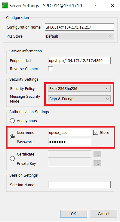
Fig. 13 . .
Connect again.
If there is a Connect Error, Ignore it to continue.
Press the Trust Server Certificate button and then check the Temporarily accept the server certificate checkbox. Press Continue.

Fig. 14 . .
If there is a Connect Error, Ignore it to continue.
Disconnect from the Server.
Allow Anonymous Connections to the Server
Connect to the PLC via Remote Desktop.
Open the TwinCAT OPC UA Configurator via Start > BECKHOFF > TF6100 OPC-UA Configurator.
Press Edit to configure the server to connect to. It is better to use the real PLC name in Server URL rather than localhost to avoid some nagging popups.

Fig. 15 . .
Click on Get Endpoints, a certificate will need to be created and a popup will emerge. Accept the defaults and press Create to continue.
Click on Add, this will add a line to the bottom table.
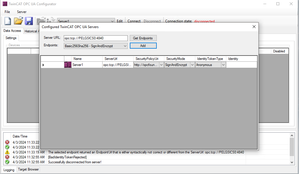
Fig. 16 . .
Double click on the server line and a popup will emerge with the details of the connection.
On the popup, you can change the Name of the server and in Identity Token Type select UserName, then in Identity please write the UserName, i.e., opcua_user, from the TrustOnFirstUse Call in the previous step.

Fig. 17 . .
Click on Ok and then close the Configured TwinCAT OPC UA Servers window. You will be back to the configurator, and the name of the connection will be displayed.

Fig. 18 . .
Click on Connect, a popup will appear. Write the Password for the user. Press OK.
The status connected should appear at Connection state.
Click on Server > Open from target to load the current configuration from the OPC UA Server.
Click on the Security tab.
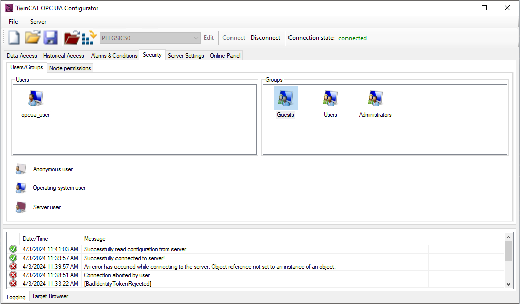
Fig. 19 . .
Right click on the Users box and select Add.
The User details popup emerges. Select None in Authentication Provider and Users in Member of group, then press Ok
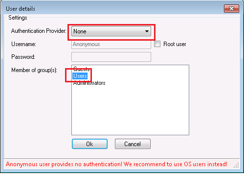
Fig. 20 . .
A new user Anonymous appears in Users
Click on the menu Server / Activate on target and select Yes to restart the Server.
Allow None as Security Policy
On the TwinCAT OPC UA Configurator click on the Server Settings tab.

Fig. 21 . .
Right-click on the Security settings box and click on Add in the popup menu.
A Configure endpoint security popup emerges. Under SecurityPolicy select SecurityPolicy#None and in MessageSecurityModes enable None. Press Ok. This will add the SecurityPolicy#None.

Fig. 22 . .
Click on the menu Server/Activate on target and click Yes to restart the server.
After this last step, UaExpert should provide a new configuration option None – None.
Connect as Anonymous and the Security Policy None-None.

Fig. 23 . .
If for some reason you would like to reinstall the OPC UA Server v5, first you should uninstall it. To be able to start from scratch, the procedure described in Chapter Uninstalling Existing OPC UA Server should be followed.
Configure OPC UA Server v5 for solutions with multiple PLC projects
In cases where the TwinCAT solution contains more than one PLC project, the OPC UA Server requires some additional configuration to properly expose variables from all projects/ports.
In TwinCAT XAE Shell confirm the port that the PLC projects are using. In the Solution Explorer double click on a particular PLC project to open the Project tab.

Fig. 24 . .
Open the OPC UA Server Configurator and connect to the OPC UA Server as opcua_user. You will have to enter the password as well.
Repeat the following for every project/port in the TwinCAT solution:
Once connected, switch to Data Access tab. There should be at least one Device configured for the default port 851. Right-click to Add a new project.

Fig. 25 . .
In the popup, enter the relevant information for your project and press OK. Pay special attention to the AdsPort and SymbolFile values, that should contain the Port of your specific PLC Project.

Fig. 26 . .
After the devices for all project ports are added, Select Server / Activate on target to update the configuration and restart the OPC UA Server.
Go to the Security tab and in the Groups window right-click on the Users group, then click on Edit.

Fig. 27 . .
In case the configuration has not been automatically added, right click on the NamespaceName table and then on Add.

Fig. 28 . .
From the Available namespaces menu, select the one that corresponds to the PLC project port you are configuring. Then, in the bottom frame click on All to give all permissions to access this namespace to the Users group.

Fig. 29 . .
Select Server / Activate on target to update the configuration and restart the OPC UA Server.

Fig. 30 . .
At this point, the OPC UA Server should expose the data from the projects you have configured. This can be checked using UaExpert, as shown in Fig. 31.

Fig. 31 . .
Configure OPC UA Server for TMC
The OPC UA Server Configurator program TcOpcUaConfigurator.exe is located under:
C:\TwinCAT\Functions\TF6100-OPC-UA\Win32\Configurator
By double-clicking on it, the configurator panel will pop up. Then one should Connect, click on Server / Open from target, and then double click on the PLC line. In most cases the user doesn’t have to do anything since the system is already configured for the TMC notation. However, it is worth checking that everything is properly configured, as shown on Fig. 32.

Fig. 32 OPC UA Server Configuration
Connecting to the Control Network
Once the PLC has been fully configured, it should be put on the control network and tested by creating a simple application with TwinCAT software.
Backup of Newly Configured System
Once it has been confirmed that the PLC is correctly configured and ready to use, it is highly recommended to do another backup of the system following the instructions given in section 4.1.
EL6688 (PTP) Configuration
This section explains how to configure terminal EL6688 in order to obtain external time references using PTP.
Assumptions:
A PTP network connection is available and ready to use.
The EL6688 hardware version is 10 or above.
The EL6688 software version is 11 or above [1].
There is another DC-capable terminal in the EtherCAT network. This terminal is the one to be used by the EtherCAT master as a reference clock.
EtherCAT cycle time: 1 ms recommended, with slower cycle times the synchronization becomes less exact.
The TwinCAT system does not update its internal time (Distributed Clocks time) but it delivers an offset to be used by the applications to derive the absolute time (UTC or TAI). Once the terminal EL6688 (see Fig. 33) has been added to the EtherCAT network, it is then possible to start its configuration following the steps described below.
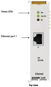
Fig. 33 Terminal EL6688 (PTP)
The hardware and software versions can be obtained from the terminal “CoE – Online” tab.

Fig. 34 EL6688 CoE-Online tab
Changing CoE Settings
The EL6688 needs to be configured to enable the reception of PTP updates from the PTP master. Follow the steps according to what is described by the Beckhoff documentation.
Set EL6688 to PREOP This should be correctly reflected in the “Current State” field under the “Online” tab, see Fig. 35.
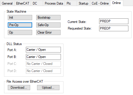
Fig. 35 EL6688 set to PREOP.
Set CoE parameters as shown in Fig. 37. Note that the IP Address in index F8E0:02 is entered as a single hex number by converting the four decimal numbers of the IP address into hex numbers. In the given example, the IP address is “192.168.1.15”. The same rule is for the Subnetmask in index F8E0:03, in this case “255.255.0.0”.
Enter the value 0x65766173 in index 1010:01. This action will save permanently the parameters in the terminal.
Set EL6688 to INIT and then to OP.

Fig. 36 EL6688 set back to OP.

Fig. 37 EL6688 Relevant configuration parameters
After doing the above steps and if everything is connected properly, the EL6688 should start receiving packets. These can be seen in the External Sync parameters below the terminal in the solution explorer, see Fig. 38. The “External device not connected” parameter shall be zero and the “Control value update toggle” shall toggle between 1 and 0.

Fig. 38 EL6688 External Sync parameters
EtherCAT Configuration
In order to use the time from the IEEE1588 network, the EtherCAT master shall be configured accordingly. The above means that DC must be in use and the option ‘DC time controlled by External Sync Device’ must be selected. This is usually done automatically by the system which will attempt to select a DC-capable terminal as the reference clock. This terminal has to be installed before the EL6688 in the EtherCAT network. Whenever possible, it is recommended to use coupler EK1110 as a reference clock. In order to access this configuration, select the EtherCAT master (“Device 1 (EtherCAT)” as shown in Fig. 39) and then select “Advanced Settings” from the “EtherCAT” tab. Once this is done, the configuration is found under “Distributed Clocks”, see the example in Fig. 40.

Fig. 39 EtherCAT master parameter window.

Fig. 40 EtherCAT DC configuration.
EL6688 Diagnostic
Under the CoE parameters of the EL6688 terminal, one could find some diagnostic data that indicates how the terminal is functioning. The “PTP State” shall be in “SLAVE (9)” for a correct operation, see the example in Fig. 41.

Fig. 41 EL6688 Diagnostic
Keeping PLC Up to Date
From time-to-time Beckhoff releases new versions of TwinCAT software. It is a good practice to follow the releases and keep the PLC SW (as well as the TwinCAT SW on the PC) up to date.
If not already done, create a Data directory on the PLC. This directory can be used to store various installation files.

Fig. 42 PLC Data Directory
TwinCAT Runtime Update
To download latest TwinCAT software, go to www.beckhoff.com and navigate to: Download/Software/TwinCAT 3/TE1xxx | Runtime and select the latest version of TwinCAT 3.1 – eXtended Automation Runtime (XAR).
After the download, unzip the file and copy it to the Data directory on the target PLC using the Remote Desktop.
Fig. 42 shows an example file TC31-XAR-Setup.3.1.4022.14.exe. Double-click on the file and follow the instructions. The update takes just a couple of minutes. At the end of the installation, the system will have to be rebooted.
A video showing how to install new version of TwinCAT Runtime can be found here.
How to Check TwinCAT Runtime Version
To check the version of currently installed TwinCAT Runtime, firstly log into the PLC. Click on the TwinCAT icon in the lower right corner and select About TwinCAT….
A window About TwinCAT System will pop up showing, among the others, the version, the performance platform and the status of the licenses (see Fig. 43).

Fig. 43 TwinCAT Runtime Version
Uninstalling Existing OPC UA Server
To properly uninstall an existing OPC UA Server, several steps should be taken. This is necessary when one wants to reinstall the server to modify some of the decisions taken during the original installation, or when migrating from Servers versions prior to version 4.4.0. The process also includes the removal of the opcua_user user.
Connect to the PLC via Remote Desktop
In Apps & Features (or Programs and Features on some machines) uninstall Beckhoff TF6100 OPC-UA Configurator
In Apps & Features (or Programs and Features on some machines) uninstall Beckhoff TF6100 OPC-UA Server
Remove the folder:
C:\TwinCAT\Functions\TF6100-OPC-UARemove the folder:
C:\ProgramData\Beckhoff\TF6100-OPC-UARemove the folder:
C:\ProgramData\Beckhoff\TF6100-OPC-UA-ServerRemove the local users opcua_user:
Right click on Start
Click on Computer management. The same can be achieved by right-clicking on Computer in the Windows Explorer and selecting Manage.
On the left pane: Local Users and Groups > Users
Delete the necessary users by right clicking on the name and selecting Delete.
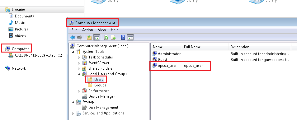
Fig. 44 . .
Reboot the PLC
Footnotes