Quality Control and
Data Processing
|
SINFONI: lamp flat
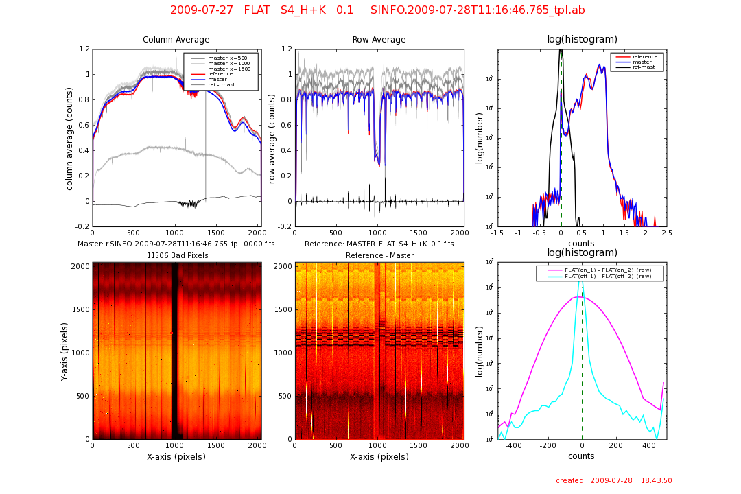
Flat frames are used to monitor the lamp efficiency in each of the available gratings/filters (J, H, K, and H+K) and pixel scales (25, 100, and 250 mas), the number of bad pixels for each grating/filter, the number of counts in the lamp-off frames, as well as the fixed-pattern-noise. For data processing flat frames are used to correct the pixel-to-pixel variations of the detector. Flat frames are routinely obtained during day-time calibrations during SINFONI operations. They are usually obtained in sets of 5 lamp-on and 5 lamp-off frames, and generally mirror the gratings and pixel scales used during the night's science observations. The SINFONI pipeline processes the lamp-on minus lamp-off frames into a master lamp flat and a bad pixel map.
~ ~  Parameters trended
The QC1 plots for the SINFONI FLATs are divided into 6 html pages, each of which shows the trending for each of the grating/filter configurations (J, H, K, and H+K) and for each of the pixel scales (25, 100, and 250 mas). The QC1 FLAT trending pages are:
Scoring&thresholds Parameters trended Lamp counts should be set such that they are above 4000 counts (for adequate S/N in the flats), and below about 10, 000 counts (to avoid any persistence effects). These limits are shown on the median lamp count trending plots as dotted lines. SINFONI FLATs have been very stable over the current lifetime of the instrument. This can best be seen the the full history FLAT trending plots shown here: FULL FLAT history.
median lamp counts: The halogen lamp flux depends on the intrinsic brightness of the lamp, as well as the chosen gratings and optical elements. The lamp-off frame is subtracted from the lamp-on frame, and the median value of the level in these 5 frames is monitored. number of bad pixels: The number of pixels in the master lamp flat having an intensity greater than a pipeline-defined threshold (default threshold is 10s). median lamp-off counts sinfoni_flat: qc.specflux.coff The lamp-off flux monitors the light and heat contamination within the optical path. The lamp-off flux levels are usually a few counts above the reset anomaly (dark) at the same DIT. This is due to the fact that the dark frames are obtained using two excluding narrow-band filters, whereas the off-lamp frames are made through a broad-band filter. The monitored flux is the median level of the 5 lamp-off frames. fixed pattern noise region 1: The fixed pattern noise is computed by fitting a Gaussian to the histogram to the master flat. The FPN is simply the standard deviation (s) of this Gaussian fit. The first FPN is computed over the central quarter of the detector [512, 512: 1536, 1536]. vignetting check: Slitlets #1 and #32 correspond to the upper-most and the lower-most slitlets in the field-of-view. As such, these slitlets can be subject to vignetting to the extent that their overall count rates can be a few 10% lower than for other slitlets. Following image reconstruction, these slitlets are located on the central part of the detector. A possible vignetting is monitored by comparing the relative count rates (i.e. the median counts in the slitlet divided by the median count rate of the entire frame) in slitlets #1 and #32 of the master flat frame. This QC1 parameter is most relevant following an instrument intervention. ~ ~
|
|||||||||||||||||||||||||||||||||||||||||||||||||||||||||||||||||||||||||||||||||||||||||||||||||||||||||||||||||||||||||||||||||||||||||||||||||||||||||||||||||||||||||||||||||||||||||||||||||||||||||||||||||||||||||||||||||||||||||||||||||||||||||||||||||||||||||||||||||||||||||||||||||||||||||||||||||||||||||||||||||||||||||||||||||||||||||||||||||||
| |
||||||||||||||||||||||||||||||||||||||||||||||||||||||||||||||||||||||||||||||||||||||||||||||||||||||||||||||||||||||||||||||||||||||||||||||||||||||||||||||||||||||||||||||||||||||||||||||||||||||||||||||||||||||||||||||||||||||||||||||||||||||||||||||||||||||||||||||||||||||||||||||||||||||||||||||||||||||||||||||||||||||||||||||||||||||||||||||||||||
 |
|
|||||||||||||||||||||||||||||||||||||||||||||||||||||||||||||||||||||||||||||||||||||||||||||||||||||||||||||||||||||||||||||||||||||||||||||||||||||||||||||||||||||||||||||||||||||||||||||||||||||||||||||||||||||||||||||||||||||||||||||||||||||||||||||||||||||||||||||||||||||||||||||||||||||||||||||||||||||||||||||||||||||||||||||||||||||||||||||||||||