| |
| QC PLOTS |
| DARK: |
CURRENT |
HISTORY |
| dark current and particle rate |
 |
 |
| |
| QC1 database (advanced users):
browse
|
plot |
Click on CURRENT to see the current trending (Health Check).
Click on HISTORY to see the historical evolution of the trending. |
The OmegaCAM dark template consists of three, one-hour exposures taken with the camera shutter closed. It is normally taken every 10 days. The processing consists of rejecting the cosmic ray events and subtracting the bias level. The remaining signal above the bias level is the dark signal, given in units of ADU/pixel/hour. For the reduction of subsequent on-sky observations the subtraction of the sky brightness will include the dark current, and a separation of both contributions is normally not required.
The pipeline creates one output frame from its dark recipe (omega_darkcurrent):
a mean dark (OC_MDAR_<date>_1_1_normal_normal.fits).
 |
An OmegaCAM mean dark (single detector) frame. The mean dark has had its mean bias level subtracted and each pixels displays its dark current in units of ADU/hour. |
top
DARK parameters trended
|
QC1 Health Check Plots
The QC1 health check plots for the OmegaCAM DARK frames consists of a single health check page. The QC1 DARK health check plots include:
- dark current averaged over all 32 extensions (ADU/pixel/hour)
- dark current for each extensions (ADU/pixel/hour)
- particle rateaveraged over all 32 extensions (particles/cm^2/hour)
QC1 parameters (trended for each individual detector)
| Parameter |
Table: Name (QC1 database) |
Description of Procedure |
| dark current |
omegacam_dark: qc.dark.current |
Tthe OmegaCAM dark template consists of three, one-hour exposures taken with the camera shutter closed. The processing consists of rejecting the cosmic ray events and subtracting the bias level. The remaining signal above the bias level is the dark signal, given in units of ADU/pixel/hour. For the reduction of subsequent on-sky observations the subtraction of the sky brightness will include the dark current, and a separation of both contributions is normally not required. |
particle rate
|
omegacam_dark: qc.particle.rate |
The particle event rate is determined by the detected number of cosmic ray events (particles/cm^2/hour). |
| difference between current and reference darks |
omegacam_dark: qc.dark.diff |
The median difference between the current and the reference dark frames (ADU). |
| average temperature of the two detector plate probes |
omegacam_dark: qc.temp.mosaic.plate |
The average value of the header temperature keyword DET.TLM5 and DET.TLM8, both of which probe the temperature of the mosaic plate (Kelvin). |
QC Reports for DARK Frames

QC Report 1:
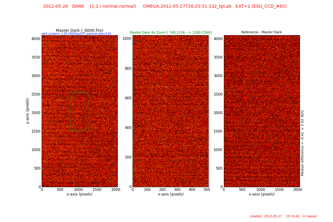
left: full-field image of the master dark of the extension listed at the top of the image
center left: 4x zoom of the center area of the master dark
right: the difference of the reference master dark and the current master dark frames. The median level of the difference image is listed to the right of the frame.

QC Report 2:
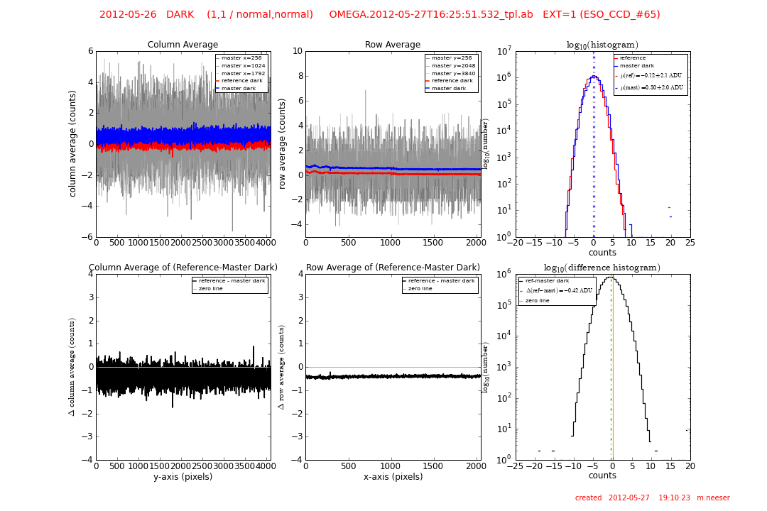
top left: a) three single column traces of the current/reference master dark through:
x = 256 (dark grey)
x = 1024 (middle grey)
x = 1792 (light grey)
b) average of all columns (normalized) of current master dark (thick blue line)
c) average of all columns (normalized) of reference master dark (thick red line)
top center: a) three single row traces of the current/reference master dark through:
y = 256 (dark grey)
y = 2048 (middle grey)
y = 3840 (light grey)
b) average of all rows (normalized) of current master dark (thick blue line)
c) average of all rows (normalized) of reference master dark (thick red line)
top right: a) logarithmic histogram of current master dark (blue line)
b) logarithmic histogram of reference master dark (red line) The median levels (as computed from a Gaussian fit) are shown as vertical dashed lines and the values are listed in the legend
lower left: difference between the average column traces of the reference and current master dark frames
lower center: difference between the average row traces of the reference and current master dark frames In both plots, the zero line is shown in orange as a reference.
lower right: logarithmic histogram of the difference between the reference and current master dark frames. Ideally, the histogram should straddle the zero line (shown in orange).
The median difference (as computed from a Gaussian fit) is shown as vertical dashed green line.

QC Report 3:
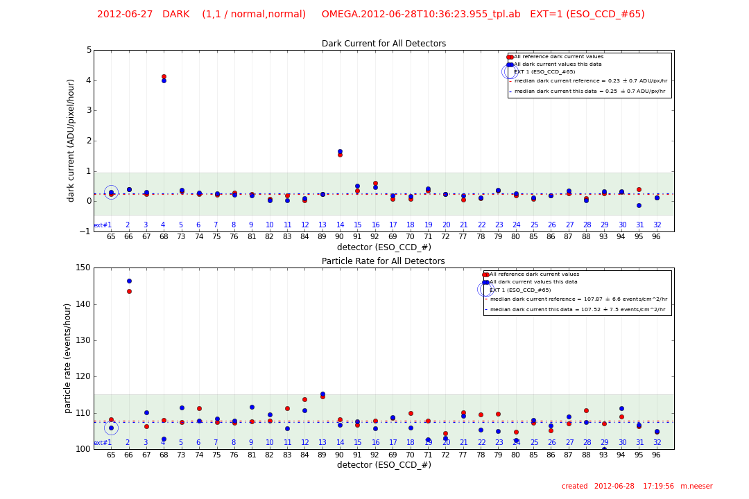
top: The dark current (ADU/pixel/hour) summarized for ALL detectors. The dark current of the detector under investigation is circled, while the reference dark current values are given as red points. The median dark current levels are given in the legend of the figure.
bottom: The particle rate (events/hour) summarized for ALL detectors. The particle rate of the current detector sampled is circled, while the reference values are given as red points. The median particle rates are given in the legend of the figure.
Trending and Issues
The master dark frames, dark current, and particle rates have been very stable for all OmegaCAM detectors.
History
|
![[ ESO ]](/images/eso-logo.gif)
![[ ESO ]](/images/eso-logo.gif)
