The OmegaCAM linearity/gain template is normally taken every 10 days and consists of 20 dome flat images taken in pairs of 2, 5, 7, 10, 20, 30, 40, 50, 60, and 70 second exposures and two bias frame exposures. The template MUST be executed in the v_STRM filter, since using the Sloan filters would result in the long exposures saturating (e.g. in z_SDSS the dome flat will saturate in 4.0 seconds).
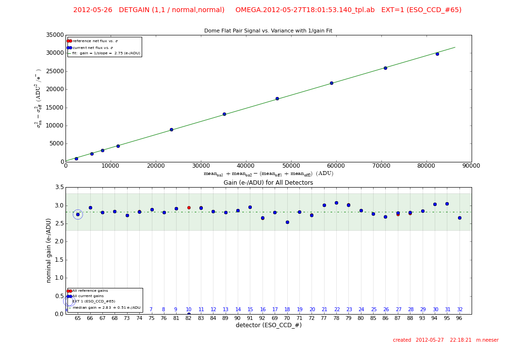
The OmegaCAM gain is derived for the full flux range. By plotting the mean_flux[on_1] + mean_flux[on_2] - (mean_flux[off_1] + mean_flux[off_2]) vs the variance (sigma^2[on] - sigma^2[off]) for each dome flat exposure pair, a linear fit to the data (green line) gives the inverse (1/gain) value.
The pipeline creates seven output frames from an external detector monitoring recipe (detmon_opt_lg):
a gain parameter fits table (OC_PDGI_<date>_1_1_normal_normal_<filter>.fits), a linearity parameter fits table (OC_PDLI_<date>_1_1_normal_normal_<filter>.fits), an image map of non-linear pixels (OC_PDNL_<date>_1_1_normal_normal_<filter>.fits), and three further images of the linearity coefficients (OC_PDC0_<date>_1_1_normal_normal_<filter>.fits, OC_PDC1_<date>_1_1_normal_normal_<filter>.fits, and OC_PDC2_<date>_1_1_normal_normal_<filter>.fits)
top GAIN & LINEARITY parameters trended |
QC1 Health Check Plots
The QC1 health check plots for the gain & linearity monitoring for OmegaCAM consist of separate gain and linearity pages.
- GAIN:
- the gain averaged over all 32 detectors (e-/ADU)
- the error in the gain averaged over all 32 detectors (e-/ADU)
- the gain for each individual detector (e-/ADU)
- score outliers
- LINEARITY:
- effective non-linearity correction averaged over all 32 detectors
- effective non-linearity correction for each individual detector
- flux level at which effective non-linearity correction is applied averaged over all 32 detectors (ADU)
- score outliers
- number of non-linear pixels averaged over all 32 detectors
- number of non-linear pixels for each individual detector
- score outliers
- minimum/maximum median flux level used in the linearity computation averaged over all 32 detectors (ADU)
- minimum/maximum median flux level used in the linearity computation for each individual detector (ADU)
- score outliers
- fixed-pattern noise averaged over all 32 detectors (ADU)
- fixed-pattern noise for each individual detector (ADU)
- score outliers
QC1 parameters (trended for each individual detector)
| Parameter |
Table: Name (QC1 database) |
Description of Procedure |
| gain |
omegacam_detlin: qc.gain |
The gain compute for each extension (e-/ADU). |
error in the gain |
omegacam_detlin: qc.gain.err |
The error in the gain compute for each extension (e-/ADU). |
| non-linearity correction |
omegacam_detlin: qc.lin.eff |
The effective non-linearity correction. |
| number of non-linear pixels |
omegacam_detlin: qc.num.bpm |
The number of non-linear pixels detected in each extension. |
| fixed pattern noise |
omegacam_detlin: qc.fpn |
The fixed pattern noise. |
| average temperature of the two detector plate probes |
omegacam_detlin: qc.temp.mosaic.plate |
The average value of the header temperature keyword DET.TLM5 and DET.TLM8, both of which probe the temperature of the mosaic plate (Kelvin). |
QC Reports for GAIN & LINEARITY frames

QC Report 1:
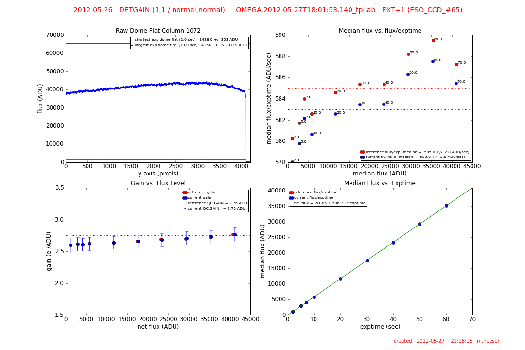
top left: a) an average column trace through the raw dome having the longest exposure time (blue line).
b) an average column trace through the raw dome having the shortest exposure time (green line).
The mean flux levels of both extremes are given in the legend and the saturation line at 65,000 ADU (red line) is also shown. The intent is to flag saturated dome flats.
top right: the median flux per exposure time (ADU/second) vs. the median total flux (ADU) for the current set of dome flats (blue points) and the reference dome flats (red points). The exposure times of each flat (2 -> 70 seconds) is listed next to each data point. The median levels are shown as dotted lines and listed in the figure legend.
lower left: the gain (electrons/ADU) vs. the net flux (ADU) for each dome flat in the gain/linearity template. The current gain values are shown with blue points, while the reference values are red. The gain levels assumed by the pipeline (QC.GAIN) are given in the legend and plotted as dotted lines. The change in gain as a function of net flux is obvious.
lower right: the median flux level (ADU) for each dome flat in the gain/linearity template vs. the exposure time is plotted for the current data (blue points) and the reference data (red points). A fit to the relation is shown as a green line and is listed in the legend.

QC Report 2:
top: by plotting the signal of dome flat pairs vs. variance one can compute the gain over the full flux range. Plotting the mean_flux[on_1] + mean_flux[on_2] - (mean_flux[off_1] + mean_flux[off_2]) vs the variance (sigma^2[on] - sigma^2[off]) for each dome flat exposure pair, a linear fit to the data (green line) gives the inverse (1/gain) gain value (e-/ADU).
bottom: the gain (e-/ADU) as measured for ALL OmegaCAM detectors. The current gain values are shown as blue dots, the reference gains are shown as red dots. The median current gain is shown as a dotted green line with its +/- 1 sigma shaded green. The current detector is circled and the median gain is listed in the legend.

QC Report 3:
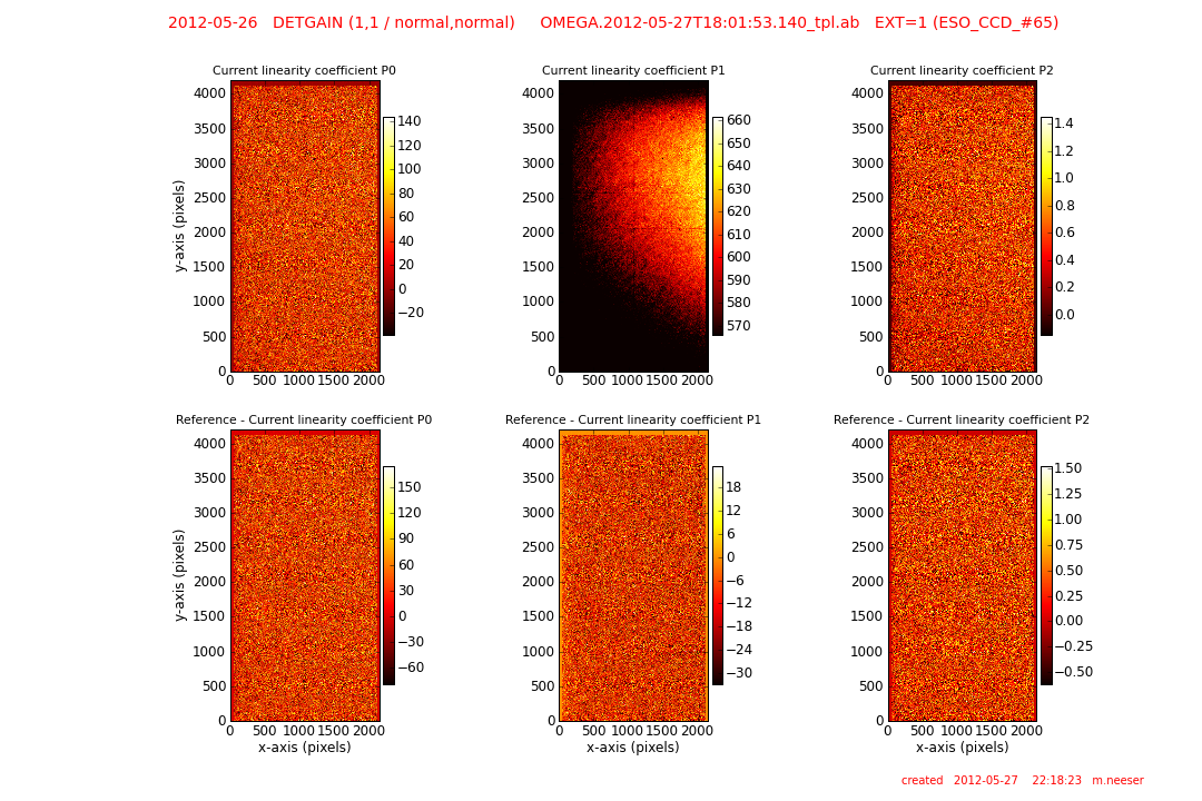
top left: the full-frame, current linearity coefficient P0.
top center: the full-frame, current linearity coefficient P1.
top right: the full-frame, current linearity coefficient P2.
lower left: the difference between the reference and the current linearity coefficient P0.
lower center: the difference between the reference and the current linearity coefficient P1.
lower right: the difference between the reference and the current linearity coefficient P2.

QC Report 4:
left: a map of the positions of non-linear pixels. The total number of non-linear pixels is listed at the top of the frame.
right: a map of the positions of non-linear pixels that differ between the reference and current non-linearity maps. The total number of differing pixels is listed at the top of the frame.
Trending and Issues
A check is always made to confirm that the longest exposure is not saturated. This will be obvious from QC report 2 which plots the trace of the shortest and longest exposure dome flats. Saturated dome flats should be rejected and Paranal advised to repeat the linearity/gain template.
History
|
![[ ESO ]](/images/eso-logo.gif)
![[ ESO ]](/images/eso-logo.gif)
