signal width QC1 plot
| HOME | INDEX | SEARCH | HELP | NEWS |
| UVES SCIENCE
reduction: signal width QC1 plot |
|||||
|
| QC1 Report: Signal FWHM | |||
|
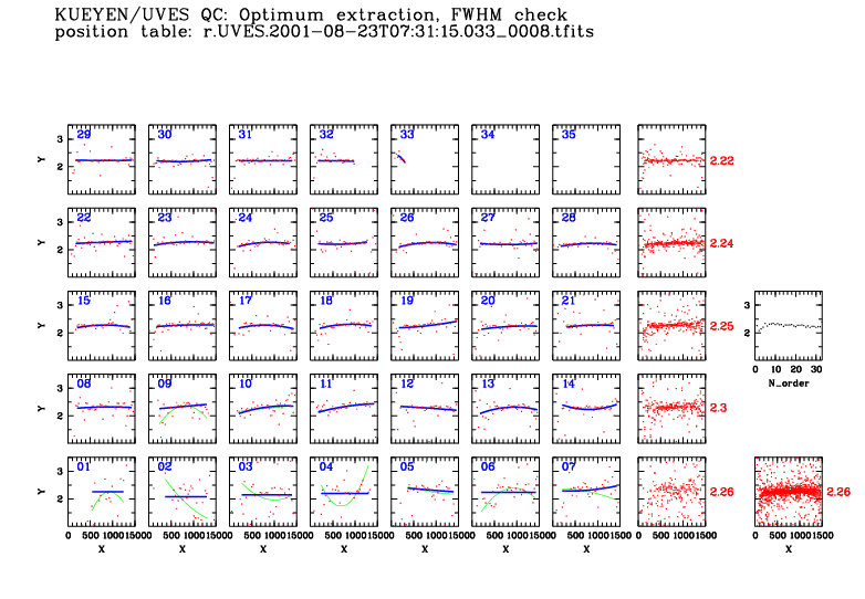
For each SCIENCE frame reduced in optimum extraction mode, the pipeline creates a result table of category "ORDER_TRACE" which contains detailed information about the position and fitted cross-dispersion width of the extracted signal. The width information is visualized in the QC1 plot "Signal width". There is one such plot per CCD (i.e. per reduced science spectrum). The information is plotted in a matrix which has seven columns for the order-by-order plots, 1 column for aggregate plots, and a final column for summary information. Find a complete sample plot for order position here. There is a tutorial on position and FWHM plots which gives more information about the proper and problematic cases.
- In the next step, a 2nd order polynomial is fitted to these values where all values with an error above a threshold are excluded. These points are taken from column :S_CH0 and plotted in green. - In the last step, a kappa-sigma routine is used to clean the FWHM values from outliers with high weight factors (small errors). The final result is in column :S_CH1 and plotted in blue. These plots are provided for each echelle order. Abscissa is X coordinate (dispersion direction) in pixels, ordinate is width in cross-dispersion direction in pixels. Inclination of the orders has been removed prior to the fitting procedure. The fitting and clipping routine has been optimized to obtain
a signal tracking and fitting solution stable against cosmic hits, bad
columns, absorption or emission lines.
|
|||
|
|
|
|
|||||
![[ fwhm_07 ]](../img/qc1_report/fwm_07.gif)
![[ fwhm_row ]](../img/qc1_report/fwm_row.gif)
![[ fwhm_all ]](../img/qc1_report/fwm_all.gif)
![[ fwhm_col ]](../img/qc1_report/fwm_col.gif) Aggregate
plots (combined view). The aggregate plots in column 8, viewed
together, permit a quick-look evaluation of certain typical extraction
problems. E.g., they show whether the 'true' cross-dispersion profile
deviates from a Gaussian, e.g. due to over-exposure or to a 2D structure
of the object. Also exposures with 'too-high' S/N can be identified
here easily (they would show a small-scale ripple structure around
the mean value).
Aggregate
plots (combined view). The aggregate plots in column 8, viewed
together, permit a quick-look evaluation of certain typical extraction
problems. E.g., they show whether the 'true' cross-dispersion profile
deviates from a Gaussian, e.g. due to over-exposure or to a 2D structure
of the object. Also exposures with 'too-high' S/N can be identified
here easily (they would show a small-scale ripple structure around
the mean value). ![[ fwhm_mean ]](../img/qc1_report/fwm_mean.gif)