A
- B - C - D - E - F - G - H - I - J - K - L - M - N - O - P - Q - R - S - T - U - V - W - X - Y - Z
1 Purpose
The purpose of this document is to provide a detailed description of all the Image Processing Algorithms and setup parameters implemented in the CCD Software Package.
This report is based on the CCD User Manual VLT-MAN-ESO-17240-0672, Issue 1.7 corresponding to the VLT Release OCT98.
2 Background
It is assumed that the reader is already familiar with the usage of the CCD Software for Technical Applications such as Auto-Guiding, Field Stabilization or any application based on TCCDS.
2.1 Coordinate Systems
We shall distinguish between two coordinate systems:
· Frame Coordinate System (FCS) : this is the physical system linked to the chip. Its origin is located at the lower left corner of the chip with coordinates (1;1).
· Window Coordinate System (WCS) : this is the system linked to the window. Its origin is located at the lower left corner of the window with coordinates (1;1). For full frame read-out, FCS and WCS are identical.
2.2 Conventions in the Formulas
In the formulas described below, the following naming conventions are used:
The pixel indices are i and j along the X- and Y-axis resp. in WCS.
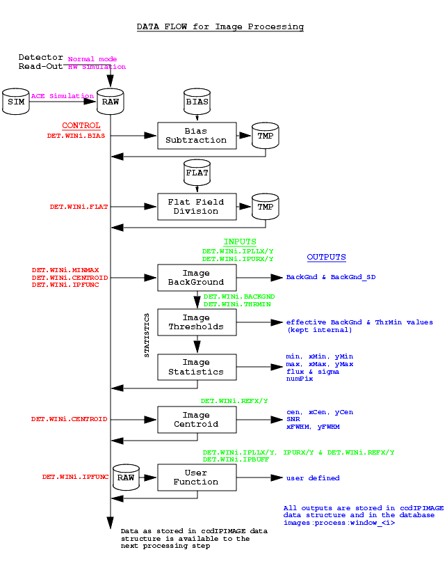
3 Data Flow
The diagram below shows the image processing data flow and the influence of the setup parameters on the processing steps:
4 Setup Parameters
A number of setup parameters describe the processing sequence of the images. Since the TCCD Systems allow the Readout of up to 2 windows, each setup parameter has its pendant on the second window. When operating the TCCD in Full Frame, the setup parameters do refer to Window #1.
Since all the processing setup keywords are named DET.WIN<i>.<XXX>, in the following only the name <XXX> will be used to refer to the parameter.
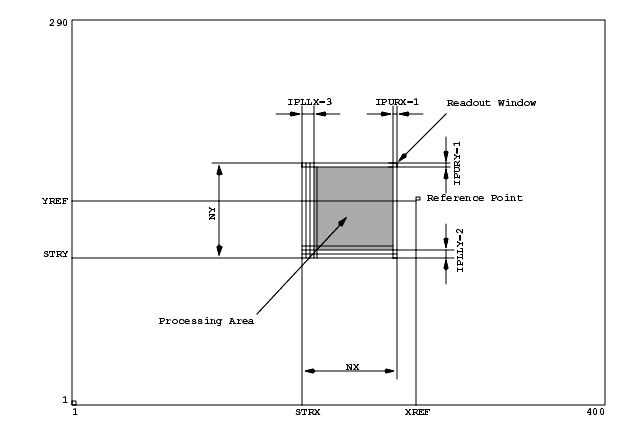
4.1 Position of the Processing Area
The setup keywords IPLLX, IPLLY, IPURX and IPURY accept positive integer values as illustrated in the diagram below:
Figure 1: Position of the Processing Area on the TCCD chip.
It is possible to locate the Processing Area anywhere inside the Readout Window; the setup parameters must verify:


4.2 The Reference Point
The position of the Reference Point (REFX ; REFY) can be anywhere on the chip. Its coordinates are expressed in Frame Coordinates FCS.
This point is used to calculate the Error Vector (see section 9.4).
4.3 Pre-Processing
Two pre-processing steps may be performed that are controlled by the logical setup keywords BIAS and FLATF.
A prerequisite to the pre-processing is that the corresponding Bias and/or Flat Field frames are available in the LCU memory.
Two possibilities are offered to get Bias and/or Flat Field images resident in the LCU memory:
· from an image file (in FITS format) located under $INS_ROOT/SYSTEM/DETDATA and named bias_<CCDNAME> or flat_<CCDNAME>. These images are automatically loaded at initialization time.
See section 6 for details.
4.4 Processing
The processing steps are controlled by the setup keywords MINMAX that performs simple statistics on the image and CENTROID that computes the position of the image centroid and additional image qualifiers. These operations are parametrized by the setup values BACKGND and THRMIN.
See sections 7 to 10 for details.
4.5 User Functions
In addition to the provided processing functions, it is possible to invoke a user function as set in IPFUNC. This function can take its arguments from a user-defined buffer IPBUFF.
See section 11 for details.
5 Data Structures
The Image Processing is designed around the C Data Structure ccdIPIMAGE defined in ccd.h.
This structure contains 4 sub-structures:
For clarity sake, the results will be referenced in the following sections with the names of the ccdIPRESULT field names.
6 Pre-Processing
The Readout Window must be contained inside the Bias and/or Flat Field images. Full overlapping checks are performed at exposure preparation time.
The resulting image is stored in the Temporary Image TMP which is used in the following processing steps. The raw detector image RAW is left unchanged. In the following sections, the pixel of coordinates (i,j) of either the RAW or the TMP image is referenced P(i,j).
6.1 Bias Subtraction
The bias subtraction is performed on each pixel of the computing frame:
The pixel indices i and j vary within [IPLLX ; NX-IPURX], resp. [IPLLY;NY-IPURY].
6.2 Flat Field Division
The Flat Field image is checked at exposure preparation time for zero pixels by the function ccdipTrapZeroes. This function logs the number of zeroes found in the frame. These pixels are forced to 1.
The bias subtraction is performed on each pixel of the computing frame:

The pixel indices i and j vary within [IPLLX ; NX-IPURX], resp. [IPLLY;NY-IPURY].
7 Image Statistics
The image statistics are computed on the RAW or TMP image and yield the following values:
and the associated standard deviation sigma:

These values are computed by the function ccdipStatistic().
8 Background Estimation
The image background BckGnd and standard deviation BckGnd_SD are estimated over the 3 less illuminated corners of the image. The formula are the same as the ones implemented in the previous section.
The size of the corners is set to 1/4 of the image size with a maximum of 20 pixels in each direction.
The background estimation is performed by the function ccdipBackground().
9 Image Centroid
The computation of the image centroid is parametrized by the setup variables BACKGND and THRMIN.
9.1 Pixel Validation
The parameters BACKGND and THRMIN determine the number of valid pixels entering in the computation. A valid pixel satisfies the condition:

where backGnd and thrMin are functions of the two setup parameters as described below:
[-11 <= N <= -19] : thrMin = -(N + 10) . sigma as estimated on the first window, only for the second window.
The conversion between the setup parameters BACKGND and THRMIN and the effective corresponding physical values backGnd and thrMin is performed by the function ccdipSetBckGndAndThrMin().
The number of valid pixels numPix is determined within the function ccdipStatistic().
9.2 Computation
The position of the centroid is computed separately on the projections of the valid pixels on each axis as the weighted average.
The projection vectors vp and hp (resp. vertical and horizontal) are assigned as described below:

The effective values of backGnd and thrMin are assigned as described in section 9.1.
The following values are computed over vp and hp:

Hence, the centroid coordinates xCen and yCen are computed in WCS system:

then in FCS, where xPos and yPos are the coordinates in FCS of the window:

and the intensity cen of the centroid is set as the intensity of the pixel the closest to the centroid.

If vsm * hsm = 0, no centroid can be computed and xCen = yCen = cen = 0.
The centroid calculation is performed by the function ccdipCentroid().
9.3 Validation
The centroid intensity cen is forced to zero whenever the centroid can not be computed, i.e. when numPix is zero. For advanced validation criteria, see User Function ccdipCV in section 11.2.
9.4 Error Vector
The Error Vector coordinates are computed as below:

10 Image Quality
Two additional parameters may help to qualify the image: the Signal-to-Noise ratio SNR and the image Full Width at Half Maximum xFWHM and yFWHM , resp. along X- and Y-axis. These parameters are estimated within the functions ccdipCentroid() and ccdipFWHM().
10.1 Signal-to-Noise Ratio
The Signal-to-Noise ratio per pixel is computed as the ratio between the integrated signal corrected of the background and the noise on the background normalized by the number of valid pixels:

10.2 Full Width at Half Maximum
The estimation of the image size along the axis is performed using the statistical distribution of intensity on the projections assumed to be normal. The standard deviation of these distributions leads to the FWHM estimation:

Note: Since the number of valid pixels is small, the statistical analysis of the projections may show a large error that biases the FWHM estimation. A more accurate method would consist in fitting a 1D Gaussian curve on the distribution.
11 User Functions
The User Function interface is described in the CCD User Manual.
The name of the function must be stored in the LCU Global Symbol Table; as well the name of the pointer to the User Buffer (if set in IPBUFF).
The image processing results as computed by the previous steps are available within the function; moreover, when processing Window #2, all results of Window #1 are accessible.
The following functions are additional functions provided by the CCD Software Package.
The User Functions receive the RAW image data.
11.1 Auto Guiding : ccdipAG
This function is based on a IRAF algorithm and consists in centering a sub-window on the image center of mass. The function returns xErr and yErr.
11.2 Centroid Validation : ccdipCV
As mentioned above, the centroid intensity may not be significant enough to decide on the validity of the centroid: e.g. assuming a noisy image with no object, the thresholds may not be strict enough to invalidate all the pixels and lead not to find a centroid. However, the SNR, FWHM or other criteria may indicate that no object is located in the image. The function ccdipCV is a multi-criteria check of the centroid validity:
· minStdDevRatio : the ratio r of the Flux Standard Deviation sigma with the Background Standard Deviation BckGnd_SDshall exceed a minimum value to be defined.
The experience shows that a ratio below 1.3 to 1.5 is a good indication for the absence of object in the frame.
· minStdDevDelta : the difference d of the two Standard Deviations sigma and BckGnd_SD shall be above a minimum value.
Any criterion set to zero is skipped.
Note : It is the responsibility of the application to check the rejectionConfidence and accordingly in-/validate the centroid.
11.3 Image Quality Estimation : ccdipIQE
This function is adapted from the function existing in SkyCat and available from RTD (PickObject).
Its algorithm is rather complex to be described herein: it consists in fitting a 2D Gaussian curve on the image thus deriving the Image Quality parameters: xErr, yErr, xCen, yCen, cen, xFWHM, yFWHM, ObjAngle, BckGnd and the Standard deviations xFWHM_SD, yFWHM_SD and BckGnd_SD.
The accuracy on the values is high but this function is CPU time consuming (see section 12).
11.4 Wave Front Coherence Estimation : ccdipWCE
This function is dedicated to the Astronomical Site Monitor (ASM). It invokes, in a loop over the stripes of the multiple exposure, the sequence Statistics + Centroid; finally it averages all the error vectors to the global one serving the autoguider.
This function stores the results in the C data structure ccdipWCEBUF that is built as described below:
in addition, for each stripe of each window, the array of ccdMAXINTEGR of the C structure ccdipSTRIPE (a subset of the structure ccdIPRESULT) that contains the following fields:
The dedicated setup variables for the Multiple Exposure of N equal stripes of lenStripe lines with an exposure time of expTime per stripe are:
The other setup parameters do not enter in the following calculations.
1. The first step consists in computing the vertical offset dl of the central line given the Reference Point (REFX; REFY):
All results are summed up and averaged by the number of stripes. These results are stored in the global image result structure ccdIPRESULT of the image and will serve to compute the Error Vector as described in section 9.4.
12 Performances
The following table indicates the performance of the various functions for the 2 supported CPUs:
|
Quadralay Corporation http://www.webworks.com Voice: (512) 719-3399 Fax: (512) 719-3606 sales@webworks.com |