Naming Conventions: In this chapter, the following naming conventions apply: the generic names devtype and Devtype differ only by the case of the first letter (lower/upper). The first case indicates the name of the device type, the latter is the name of the device type when concatenated with the module prefix as in appDevtype.
As of this issue, lsf supports the following devices:
Architecture: The purpose of a framework is to impose the architecture of the applications based on and to provide the implementation of the standard behaviour. The application is consequently responsible for implementing the specialized functionality as of its design.
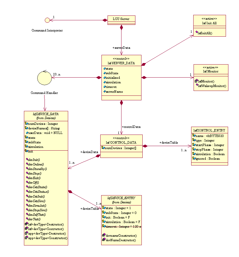
The architecture is hierarchical: The server object lsfServer is responsible for handling the application global data and hosts the commands of the application; these commands might involve no device (pure software command) or devices of various types (combined command). The actual control of the devices is performed from within the object lsfControl that dispatches the standard commands to the respective devices. Finally for each device type, an object lsfDeviceType implements the commands of this type of device.
Two additional objects complete this view: the task lsfInitAll that creates the application at boot time, and the task lsfMonitor, created at boot time, that monitors periodically the state and sub-state of all the devices and updates consequently the state and sub-state of the application.
Devices: Each device is characterized by its type as listed above. All devices of one type are supposed to behave in a similar manner in response to the standard commands. Consequently all the methods associated to one device type perform the same actions on all the devices of this type.
Standard Behaviour: The standard commands are implemented within the framework. They define the standard behaviour of each standard command for each type of device. The standard behaviour is edicted in [RDV 02] for Software Devices and State management. The standard behaviour can not be modified but only extended by means of dedicated hooks functions, which are application specific and implement additional actions required by the application design (e.g. set a particular I/O signal prior to go Online).
States and Sub-States: Each device is characterized by its state and sub-state.
The state is defined by LCC ([RDV 02]) and
takes the values OFF,
LOADED,
STANDBY or ONLINE.
Each group of devices of a type is as well characterized by a state and sub-state value;
the state is set as being the lowest state of all the devices of this group.
The global application state is then the lowest state value of all the devices.

The sub-state is used to indicate the detailed activity of a device, or group of devices; the following sub-states have been introduced:
The 2 sub-states Error and Timeout are transcient states that reset to Idle on recovery, or on next request.
The global sub-state of the software device is set to:
Database: All relevant configuration and runtime data is stored in the OLDB of the LCU, which is partly mirrored on the WS so as to enable the use of the scan system.
Each type of device is mapped in the database by a dedicated class. All the device classes are derived from the base abstract class lsfDB_DEVICE as depicted in the class hierarchy:

Note that a Software Device is a sub-class of lsfDB_SOFTDEV, thus allowing recursive construction: a Software Device can be a sub-Software Device of another one.
The structure of the database is fixed as illustrated in the diagram below:

Note the multiplicity of the various instances as a means to scale the database to the exact needs of the application.
Application Data: The class lsfDB_DATA is an abstract class. It does not contain any attribute as it is intended to be specialized (by sub-classing) to the needs of the application. This class has been introduced so as to allow the application to store data that shows following characteristics at a known location:
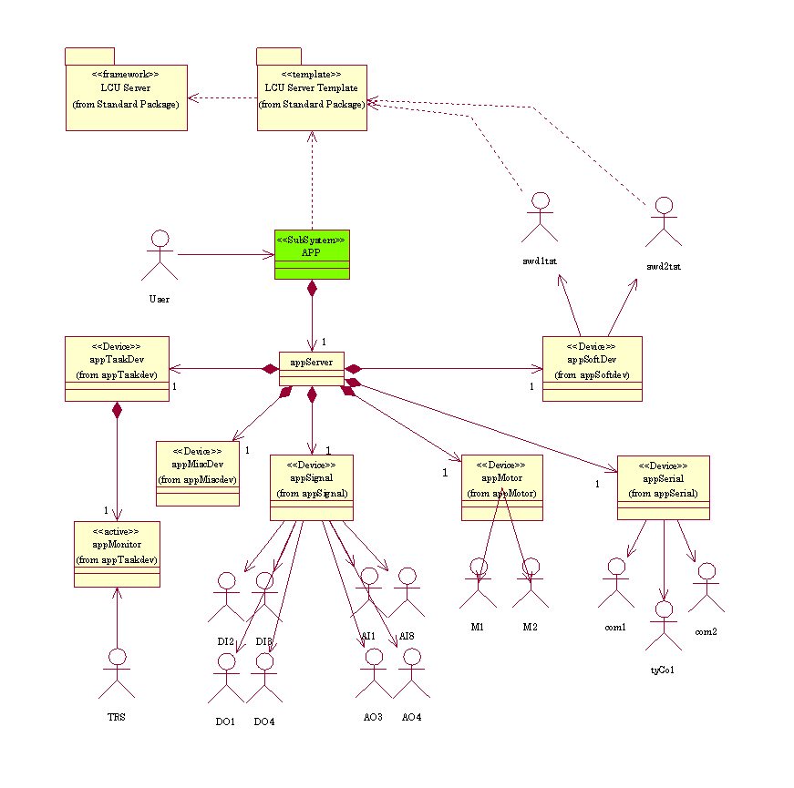
The module lsftpl is a template application based on lsf that provides an implementation template for all available device types. In particular, it gives examples of ACI and API functions for signals and motors for addressing one or all devices of this type.
The template implements the control of 16 devices: 8 I/O signals (4 analogue and 4 digital where from 2 input and 2 output signals), 2 motors, 3 serial communication links (2 using the ISER 8 board, and one /tyCo device), 2 sub-ordinated software devices (swdtst1 and swdtst2) and 1 task device performing periodic monitoring) as illustrated in the class diagram below:
It implements the functionality as shown in the Use Case diagram:
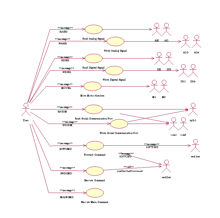
N.B.: as of this version, both the encoder and network devices are not yet supported.
The following section describes all the steps necessary to create a new application from this template.
This section describes how to create a LCU Server Application based on the Framework.
It assumes the detailed analysis of the package is complete: all interacting devices, and commands and interfaces have been identified and described.
The creation of a new LCU Server Application app from the template is made by means of the utility lsfCreate(1). It makes a copy of the template module lsftpl in its last version available under CMM, and performs all string replacements: all occurences of lsftpl are substituted by app, as well the occurences of LSFTPL are substituted by APP.
Example:
The module app is ready. It needs now be configured for the devices and commands.
The configuration of the application is kept central in the file app/ws/config/app.cfg. This file must be edited to the needs of the application. The module configuration contains 3 parts:
Example:
#*****************************************************************************
# E.S.O. - VLT project
#
# "@(#) $Id: UserManual.html,v 1.4 2002/07/10 12:05:29 vltsccm Exp $"
#
# who       when        what
# --------  ----------  ----------------------------------------------
# pduhoux   2000-04-07  created
#

#
# MODULE
#
LSF.MODULE.NAME     app

#
# DEVICES
#
LSF.DEVICE.NUM      1

LSF.DEVICE1.NAME    NDF
LSF.DEVICE1.TYPE    motor
LSF.DEVICE1.CLASS   motDVAMI
LSF.DEVICE1.PARAM   P 7,V 3,I 6

#
# COMMANDS
#
LSF.COMMAND.NUM       1

LSF.COMMAND1.NAME     SETNDF
LSF.COMMAND1.DEST     motor
LSF.COMMAND1.GROUP    PUBLIC
LSF.COMMAND1.ENTRY    SetFilter
LSF.COMMAND1.INVOKE   TASK
LSF.COMMAND1.OPTION   appSETNDF,,,40000

# ___oOo___
The effective configuration of the LCU Server Application app is made by means of the utility lsfConfig(1).
It performs following steps:
Important Note: The utility lsfConfig shall be called once as its actions are destructive for some files. Any application dependent modification made to the partial CDT files will be lost during this process, as these files are re-created. A posteriori addition of a device of a new type is not supported.
Example:
> lsfConfig app
Parse file 'app/ws/config/app.cfg' ... done
Found 1 device:
     1 Motor    : NDF
Found 1 PUBLIC command:
     1 Motor    : SETNDF
Found 0 MAINTENANCE command
Found 0 TEST command
Generate 'app/ws/config/app.dbcfg' ... done
Generate 'app/lcu/include/appDeviceList.h' ... done
Generate 'app/lcu/dbl/app.db' ... done
Generate 'app/lcu/src/Makefile' ... done
Generate 'app/lcu/src/appPublic.cdt' ... done
Generate 'app/lcu/src/appMotor.cit' ... done
Move unused files to ./lcu/tmp ... done
Add change log entry ... done

>>> Remember to edit the CDT files ...

Module configuration for 'app' ... done"
>
After the module has been tailored to the needs of the application, some files need be edited to implement the behaviour and specify the interfaces as of the design.
For the sake of clarity, one might group the API functions dedicated to one specific device into one separate file. These files may be included into the device type associated file.
The class diagram shown below depicts the device control structure for a specific command:

For application implementing the WS counterpart of the database, the scan links must be configured. These links are described in the file app/ws/config/app.scan.
At boot-time, the database branch of the module need be configured. The configuration is kept in the file app/ws/config/app.dbcfg and restored at startup with the following precedence order from:
Example:
> cd app/ws/config
> lsfBackup -e lcuEnv -m app
Generating input file './app.inp' ... done
Performing database backup into  './app.dbcfg' ... done
>
The file ./app.inp is a temporary file that contains the list of database points and attributes to backup. At backup completion, it is removed.
A default panel appgui is provided by the template that instantiates the UIF widget lsfState_uifClass. This widget shows the associated LCU environment name, a button for sending standard commands, a STOP button, and the status information of the module (state, subState and operational mode).
In addition, the Command Feedback Window shows the last 2 replies.
The WS part is built as described in app/ws/src/Makefile. It makes the panel app/ws/src/appgui.pan and installs the two configuration files app/ws/config/app.scan and app/ws/config/app.dbcfg under $XXXROOT/config.
Example:
> cd app/ws/src
> make all install
 ...
 . . . 'all' done
 ...
 . . . installation done
>
The LCU part is built as described in app/lcu/src/Makefile.
It invokes 3 utilities prior to building the code (target "all"):
Example:
> cd app/lcu/src
> make all
 . . . 'CIT' done
 . . . 'CDT' done
Include file '../include/appMotorInterface.h' done
 . . . 'include files' done
 ...
== Building executable: ../bin/app

 . . . 'all' done
>
Note: The final CDT and CIT files are deleted by the Makefile. Remember to perform the modifications in the ./src directory.
As stated in the rules applying to a Software Device, the behaviour of each command is implemented in a Command Handler. This handler must show the 2 ACI and API interfaces:
      ccsCOMPL_STAT Iapp<Devtype><Entry>
                               ( ... , ccsERROR *error )
It is responsible for parsing the command parameters, invoking the API function and building the
reply buffer as defined in the CDT entry of this command.
      ccsCOMPL_STAT app<Devtype><Entry>
                               ( ... , ccsERROR *error )
It is the core implementation of the behaviour of the command. It must be callable
from another application. It receives application specific parameters and the
error stack pointer, and returns the completion status.
A hook function is implementing an additional behaviour. Four kinds of hooks are supported:
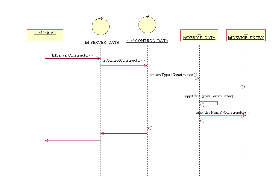
The application specific constructors have the prototype:
ccsCOMPL_STAT app<devType>Constructor ( IN  void       *devData,
	                                IN  const char *devName,
	                                OUT ccsERROR   *error )
ccsCOMPL_STAT app<devName>Constructor ( IN  void       *devData,
	                                IN  const char *devName,
	                                OUT ccsERROR   *error )
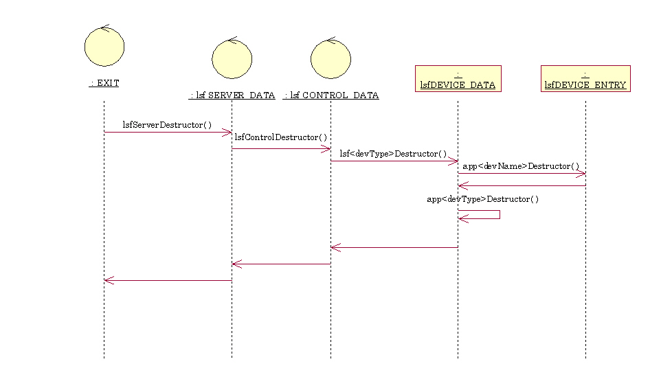
The application specific destructors have the prototype:
ccsCOMPL_STAT app<devType>Destructor  ( IN  void *devData )
ccsCOMPL_STAT app<devName>Destructor  ( IN  void *devData )
ccsCOMPL_STAT appStd<Command><Type>Hook ( IN  lsfSERVER_DATA *serverData,
                                          OUT ccsERROR       *error )
where Command is the name of the command
(Init,
Standby,
Online,
Stop,
Off,
Exit,
Selftest,
Test),The hooks are located in the file appStdHooks.c. They do not need any prototype declaration.

ccsCOMPL_STAT appSignalInitHook ( IN  lsfSIGNAL_DATA *signalData,
                                  IN  const char     *signalName,
                                  OUT ccsERROR       *error )
ccsCOMPL_STAT app<TaskDevName> ( IN  lsfTASKDEV_DATA *taskDevData,
                                 IN  const char      *taskDevName,
                                 OUT ccsERROR        *error )
where TaskDevName is the name of the task device
(starting with upper case).
ccsCOMPL_STAT app<TaskDevName>ProHook ( IN  lsfTASKDEV_DATA *taskDevData,
                                        IN  const char      *taskDevName,
                                        OUT ccsERROR        *error )
resp.
ccsCOMPL_STAT app<TaskDevName>EpiHook ( IN  lsfTASKDEV_DATA *taskDevData,
                                        IN  const char      *taskDevName,
                                        OUT ccsERROR        *error )