| X-ray
Catalogue |
LogN-LogS |
Sky
coverage |
| Obs. ID | Obs. Date | Exposure Time (ks)a |
Roll Angle | Aim Point | Count Rateb |
| 1431-0... | 1999 Oct 15 | 24.983 | 47.28 | 3 32 29.4, -27 48 21.8 | 0.980 |
| 1431-1... | 1999 Nov 23 | 92.807 | 47.28 | 3 32 29.4, -27 48 21.8 | 0.7846 |
| 441... | 2000 May 27 | 55.727 | 166.73 | 3 32 26.8, -27 48 17.4 | 0.6812 |
| 582... | 2000 Jun 03 | 129.869 | 162.93 | 3 32 26.8, -27 48 16.4 | 0.6984 |
| 2406... | 2000 Dec 10 | 29.564 | 332.18 | 3 32 28.4, -27 48 39.3 | 0.668 |
| 2405... | 2000 Dec 11 | 59.363 | 331.81 | 3 32 29.0, -27 48 46.4 | 0.670 |
| 2312... | 2000 Dec 13 | 123.212 | 329.92 | 3 32 28.4, -27 48 39.8 | 0.6528 |
| 1672... | 2000 Dec 16 | 94.564 | 326.90 | 3 32 28.9, -27 48 47.5 | 0.6589 |
| 2409... | 2000 Dec 19 | 68.719 | 319.21 | 3 32 28.2, -27 48 41.8 | 0.6570 |
| 2313... | 2000 Dec 21 | 129.937 | 319.21 | 3 32 28.2, -27 48 41.9 | 0.65487 |
| 2239... | 2000 Dec 23 | 130.250 | 319.21 | 3 32 28.2, -27 48 41.8 | 0.674 |
b Count rates on four ACIS-I CCD (0.5
 7 keV).
To detect sources in the Chandra Deep Field South we ran a modified version of the SExtractor algorithm (Bertin & Arnouts 1996) on the 0.5
 7 keV image. This modified detection
algorithm is several orders of magnitude faster than
the wavelet algorithm of Rosati et al. (1995)
or WAVDETECT in the CIAO software (Dobrzycki et
al. 1999; Freeman et al. 2002).
Detection parameters (e.g., threshold, characteristic object
size, and ultimately the signal-to-noise) were chosen to
find very faint sources, while limiting the number
of spurious sources to 10, or approximately
  3% of the total sample.
The number of fake sources as a function of the algorithms' parameters was determined via extensive simulations as described in Tozzi et al. (2001). For a detailed desrcption of the detection procedure see Giacconi et al. (2002).
|
1 Msec Catalogue |
LogN-LogS
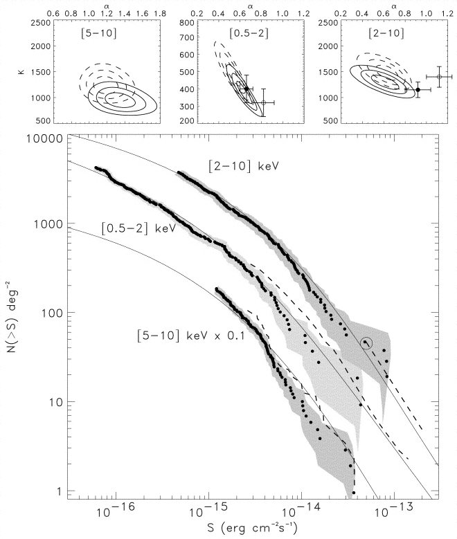
Rosati et al. (2002)
log N-log S in the soft (0.5
 2 keV), hard (2
 10 keV), and very hard (5
 10 keV) bands from the 1
Ms observations of the CDF-S. The shaded areas
indicate uncertainties due to the Poisson statistics (1
 ) and the choice of the
conversion factor (corresponding to a power law
spectrum with
  = 1.4 ± 0.3). Dashed lines
are previous measurements: ROSAT deep surveys
in the 0.5
 2 keV band (Hasinger et al.
1998),
ASCA surveys in the 2
 10 keV band (Cagnoni et al. 1998;
Della Ceca et al. 1999),
and the recent XMM Lockman Hole observation
in the 5
 10 keV band (Hasinger et al.
2001).
Solid lines are predictions from model B by
Gilli et al. (2001)
(see text for details). The three top panels
show the likelihood contours for the best-fit
normalization and slope of the faint end in the
three bands from the CDF-S (solid line) and
CDF-N (dashed line) data. Data points refer to the
best-fit values of Tozzi et al. (2001)
(300 ks; filled circles) and the Lynx field (190
ks; Stern et al. 2002;
open circles).
 |
| Soft
[0.5-2 keV] |
Hard [2-10
keV] |
Very hard
[5-10 keV] |
Sky coverage
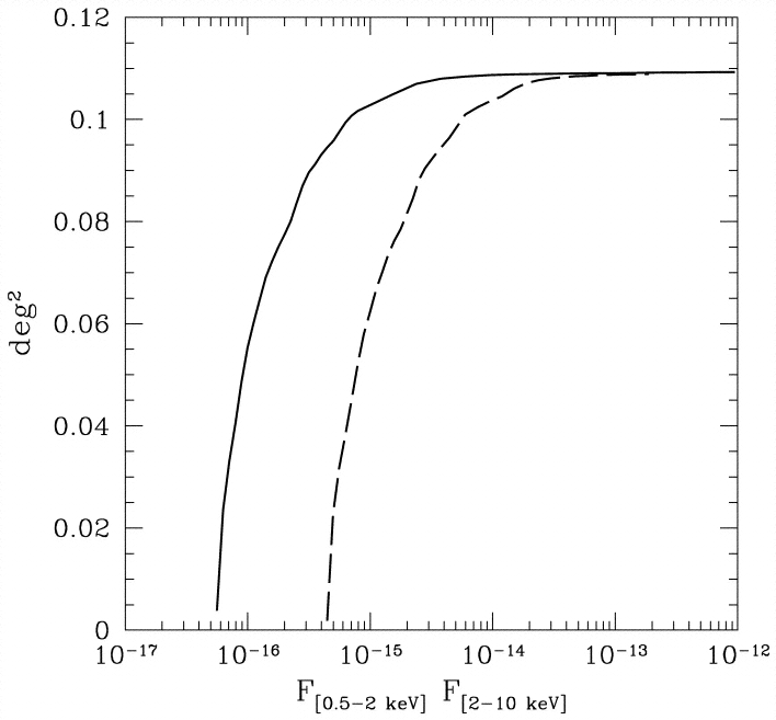
Giacconi et al. (2002)
The sky coverage (area covered vs. flux limit) for the soft image (solid line) and the hard image (dashed line). The sky coverage is plotted against the 2
 10 keV energy flux which is actually
used in the catalog.
 |
| Soft
[0.5-2 keV] |
Hard
[2-10 keV] |
Very
hard [5-10 keV] |
Detection band [0.5-7] keV...................... FITS
Soft band [0.5-2] keV............................... FITS
Hard band [2-10] keV............................. FITS
Adaptive smooth [0.5-7] keV.................. FITS ........ GIF
Exposure maps are computed in the
soft (0.5-2) and hard (2-7 keV) bands for a typical power law spectrum
with Gamma = 1.4 (which is the average spectrum of the XRB and
therefore of the sources detected in the CDFS). Exposure map [0.5-2] keV...................... FITS
Exposure map [2-7] keV...................... FITS
Area map [0.5-2] keV...................... FITS
Area map [2-7] keV...................... FITS
Time map [0.5-2] keV...................... FITS
Time map [2-7] keV...................... FITS
Exposure maps
The units are [sec *cm2].
By dividing the expmaps by the total exposure time (935965.6
sec) we obtained the areamap (in cm2), while dividing the expamp by
the maximum effective area in each band, we obtained the timemaps (in
sec), which give the effective exposure time. By dividing the net
detected counts by the exptime (as given by the Timemaps), one can obtain the net count rate corrected
for vignetting.