2 USER'S GUIDE
2.1 Overview
The VLT architecture relies on an On-Line database (DB) that provides real-time data capabilities on a distributed architecture[2].
As a consequence, a relevant part of the design of the VLT is the design of the sections of this database distributed on the different Workstations and LCUs.
Each local database has a hierarchical structure mapping the physical objects that constitute the telescope system (instruments, telescope control components....) and describing how they are logically contained one inside the other (how one component is "part-of" another one).
Each local database has a partial image only of the units of the system that the particular WS or LCU has to use. These components can be true property of the Workstation or LCU itself, or can be just images locally maintained for performance reasons, so that it is not necessary to ask for data through the network every time. The whole database is the merge of all the local sections.
This means that the global database comprehending all the Workstations and LCUs will have often different images for the same physical objects (usually a complete one for the LCU that handles it and a partial one for the WS controlling that LCU).
At the same time there will be a lot of different places in the database describing objects with the same or with a very similar internal structure and behavior. For example, the VLT system will have a lot of motors, decoders or moving axis that have the same general characteristics and can be represented in a logical tree; here common logical parts can be grouped together and the designer can describe only the differences that characterize the peculiarities of each object.
Using an Object-Oriented terminology, inside the database there are a lot of different instances of the same class (such as motors and encoders) or of similar classes (different kinds of motors), and different images of the same object: a "model" describing the full properties of the object (usually on the LCU's database) and some partial "views" (usually on a control Workstation), containing only what is necessary to control the device from outside.
2.2 Design, development and maintenance requirements
To help the database design, development and maintenance phases during the lifetime of the VLT project, it is necessary to have tools able to automate and enforce the implementation of the concepts introduced in the previous paragraph.
2.2.1 Database design
During the design phase of the database, it is necessary to have access to a common repository of templates for the description of the different modules than can be reused by various parts of the VLT, introducing some peculiar characteristics where necessary. The concept of class helps a lot in this task:
· a wide library of classes describing objects commonly used is available. These can be simple basic components (such as I/O signals, encoders, motors) or higher level parts (such as axis, CCD devices...);
· a component of the VLT completely described by a class is created with just a reference to the class, with the setting for initial values where necessary;
· an object that is different just for some aspects with respect to an instance of the class is created making a reference to the class and describing what it has more and/or different: all the rest is inherited from the base class;
· a new object useful for reuse becomes a class in itself and is readily available to all other potential users;
· the description of a class is not a flat entity, but it can contain, as internal members, objects of other classes, for example an axis contains an encoder, a control loop and a motor.
Having these concepts implemented, it will help a lot the designers to create similar database structures, uniform for the whole VLT project, and in reusing the code sharing knowledge.
2.2.2 Database development
Once a proper design has been done, the development of the true database must be a straightforward process.
To get this result, a simple description language is necessary for the database structure that:
2.2.3 Database maintenance
During the maintenance phase there is often the need of modifying the characteristics or the behavior of an entity that has been used in many different places.
It is therefore necessary a support to modify the general description (i.e. the class description) in a way that the modification is automatically applied to all the instances.
At the same time, the modification has to be applied automatically to all the sub-classes.
This means that the simple copy-and-paste technique, where there is a template and new classes or instances are obtained copying and modifying it, cannot be used. This technique is at the same time tedious and error prone:
· it is difficult not to forget to propagate some modification manually or not to introduce errors while doing this
It is also important to have in the same place the description for all the different views of the same object, in order to have a better control of it while making minor modifications.
2.3 Rtap Database structure
The local branches of the On-line database on the Workstations are based on the commercial hierarchical real-time database of Rtap[7]. The second part of the database is distributed on the LCUs and has been developed in order to be compatible with the Rtap implementation for what concerns the general structure and the syntax used for the point configuration files; these are the ways to describe the database structure to the system[4][5].
The description of a database is a directory tree on the Unix or VxWorks filesystem: every directory represents a database point and contains a configuration file describing the point characteristics and subdirectories for the description of sub-points.
The design and development of a database consist of building the directory tree.
The concept of template is implemented having standard trees of point description files that can be copied in a specific position and modified by hand.
Obviously this approach cannot give any automatic support for inheritance and suffers for all the problems mentioned in the previous paragraph about copy-and-paste technique.
2.4 Class support extension
The requirements described in the previous paragraphs are implemented extending the syntax of the Rtap point configuration files.
Using this extension a single file can describe a full database branch, and thus gets the name of "branch configuration file".
It implements the concept of class using inheritance to derive new classes and to get instances of classes.
The dbl tool reads "branch configuration files" as input and generates the corresponding database in the form of Rtap standard "point configuration files", resolving all the dependencies between classes.
The actual database points will have some special internal structure used to implement features related with class inheritance, but these will remain generally hidden to the user and will not have a relevant impact on access performances.
2.4.1 Branch definition
The branch configuration file has to describe a full branch of the database. The full database of a Workstation or of a LCU is built loading one or more branch config files with the loader tool. The loader takes care of checking that all the branches are coherent.
This means that a branch config file contains the description of all the objects that are logically contained (i.e. subject to a "part-of" relation) inside a single entity.
Each branch config files contains:
The most important general definition is the database path of the root point for the whole branch. It is called the BranchRoot point. Each point described in the file has to be inside the branch starting from it. The default BranchRoot is the local database root.
Using the features of the C preprocessor it is possible to make use of conditional compilation and #define directives to have different BranchRoot points, in order to compile the same file for alternative views of the branch.
A typical example is when defining a sub-branch for a whole LCU (LTE23 in the example). On the database of the LCU itself, the file will describe the complete database, on the control Workstation it will be loaded as a sub-branch of the whole WS database.
The more convenient approach is to have a single configuration file for both these implementations of the database.
#define directives can help to make more general the code and the usage of the #include directive help to implement common conventions.
Once defined the reference BranchRoot, the config file contains the list of point definitions.
It can also contain definitions for local classes, used only in the scope of this configuration file.
2.4.2 Point definition
The points are the true objects that have to be put in the database to describe the system.
Usually they have to be instances of a class. The main target of this approach is in fact to have an extensible library of classes able to fullfil all the needs of the model: new requirements must be satisfied designing new classes or changing the characteristics of already existing ones. This is the key to have a uniform environment within all the parts of the database and to maintain it without manual intervention.
In the simplest case, it is necessary only to declare a point as an instance of the desired class. The loader will take care of retrieving the class definition, creating the point with all the attributes inherited from the parent class and its ancestors and assigning the initial values to the attributes:
where ClassName is the name for the class of the point and point_name is the name given to the instance (it can be a database path name relative to BranchRoot, but all the intermediate points in the path must have already been defined). A point can be defined "on the fly", without inheriting from any class. In this case ClassName must be replaced by NULL_CLASS(3.1.8).
Consider the common example of a point used to get a temperature value from an input channel. This task can be accomplished using a point of class TEMPERATURE_INPUT. This is a specialized sub-class of a more generic ANALOG_INPUT.
In the simple example in which we have just to use an instance of TEMPERATURE_INPUT, without having to modify anything, we can simply declare it in the short form:
The loader will add to the DB a point (child of BranchRoot) with all the characteristics inherited by the TEMPERATURE_INPUT class and its ancestors; for example the new point will have attributes to deal with:
Using this technique will ensure that all the points used to collect temperature values in the whole VLT database will have the same structure and behavior. The access techniques to the point can at the same time be standardized and be implemented via commonly accessible "class methods", implemented through a library of C or C++ access functions, with obvious advantages in terms of code reuse and maintainability.
In some cases it is necessary to assign special initial values to some of the inherited attributes, to configure the initial status of the point.
This can be done using an extended point declaration format:
Inside the BEGIN ... END area, it is possible:
· add new attributes that will be placed only in this specific point instance, without the need of defining a new class
All the attributes not specifically declared will be inherited without changes.
For example, the TEMPERATURE_INPUT class inherits from its parent ANALOG_INPUT the ability of generating alarms when the monitored value becomes higher than a specified limit (defaulted to 100 arbitrary units). In our specific instance the limit has to change to 50 arbitrary units, because the device where it is installed is more sensitive to heating effects. This can be done using the extended syntax:
The special behavior of the object is described only in terms of differences from the standard class.
If a declared attribute already exists in the list of inherited ones the new value is assigned, provided that the new declaration is coherent (i.e. it is different only for characteristics that can be overloaded, such as the value in this case). If an attribute with the same name does not exist, a new one is added to the point.
2.4.3 Class definition and inheritance
From a logical point of view, a class is a data type able to describe structured structures, just like an integer attribute is able to describe an elementary entity.
The class definition can thus be considered as a definition of a new structured data type and this will be used as any other available data type. This means that a class instance can be used just in the same way as a native type (it is called a class-type) while defining attributes inside classes or points. It is then possible to build hierarchies of points logically contained one inside the other.
For example, every tracking axis will contain an encoder, a control loop and a drive (that are library-provided classes): this structure must be described while defining the class for the tracking axis and the declaration of a point of this new type must automatically generate the sub-points, just in the same way it generates the normal attributes.
Each new class has to be derived from another class, from which it inherits all the properties, in terms of attributes and behavior. Beyond just inheriting attributes, a class definition may:
The basic class that must appear as an anchestor for every other class is BASE_CLASS (2.4.3): it implements only the internal behavior used to support the class concept inside the Rtap DB.
Class definitions could be inserted directly in the branch configuration files, but should be put in separate files (one per class), placed in a common search path and examined automatically by the loader while resolving class dependencies.
The class definition syntax resembles the syntax used to define points:
where all the attributes definitions (basic types or class types) are placed in the class description.
A class definition consists not only in the data description that will be loaded on the database, but also in the behavior of the class: this is implemented defining a library of C functions or a C++ access class associated with the database class. Actions on the data stored in the points will be executed using these methods. The simplest examples are read and write operations, performed through methods instead of the plain dbRead() and dbWrite() functions. This warranties that only allowed operations are executed and that the object itself can perform all the necessary checks before arbitrarily changing attribute values.
Since every CCD will have such a parameter, it will be defined as an attribute of the CCD base class and there will be several instances of it in the VLT database.
At the same time the exposure time is not a plain floating point variable: it is an entity characterized by:
- every time someone tries to change the value, it must be checked against the limit values and accepted or rejected.
The correct implementation for this configuration defines the CCD base class as containing and instance of the library-provided EXPOSURE_TIME class:
This will completely define the expTime attribute inside the class, giving it a standard structure, common to all the other instances, also if developed by other people. Standard implementation and code reuse is enforced by the presence of classes and no more left to the database designer: a class definition is placed in unique "class description file" available for immediate usage by anyone and centrally maintainable. Thus the class can be considered more error safe than a new implementation from scratch.
Grouping the classes in logical hierarchies where common characteristics are defined in a unique entity at an higher level of abstraction (a super-class) carries on a lot of advantages, as already put in evidence.
Another important aspect is that it also helps to identify the responsibilities of each entity, making easier to apply the general principle that "knowledge" should be concentrated on as few places as possible, and on a hierachical level as high as possible and as low as necessary (but not lower!). It often happens that some different entities provide the same kind of services, but they have to be implemented in several different ways. This means that these entities have a common logical root, but have at the same time some peculiar properties.
A good way to model these concepts is to have a common base class defining the services, and the specific subclasses implementing them. The user asks for the service without worrying about the way it will be satisfied: it is full responsibility of the sub-class implementer, the only entity with all the necessary knowledge. This kind of behavior (commonly called polymorphism) is implemented by defining a C++ access class to provide methods and using C++ inheritance in subclasses.
In the previous example we have made use of an instance of the EXPOSURE_TIME class, without worrying about its class-hierarchy.
In the VLT class library this class is not an immediate descendant of BASE_CLASS, but it is just a leaf in a hierarchy of classes that implements the basic (and widely used) concept of range-controlled value.
All the classes in the hierarchy represent a variable that has to be checked and whose allowed values are within a specified range.
This is a general concept, implemented in the base class; the actual type of the value (integer, floating point, character string....) and the type of range (boolean, min-max analog, min-max digital, one of a list...) are defined in the specific sub-classes.
The following diagram shows some of the classes in the hierarchy (ready to be used by everyone to create instances or new sub-classes):
The ANALOG_VALUE and DIGITAL_VALUE classes handles values that can accept only an analog (floating point) or digital (discrete, with a predefined step, by default integer) value, within a specified min-max range, so they are both sub-classes of MIN_MAX_VALUE, where the attributes are defined.
To use these classes it is just necessary to create an instance (or a specialized sub-class) and set the limit values:
By the way the values are often the readout or readin for some device, and therefore they have some physical unit and unit conversion rules, as well as physically meaningful range definitions. In this case it is much better to use specifically designed classes such as EXPOSURE_TIME or TEMPERATURE:
On the other branch of the hierarchy are CHOICE_VALUE classes, where the stored value can have only a value chosen within a predefined list. In this case it is necessary only to overload the table with a new one initialized with the selectable values.
to ask an instance respectively to assume a new value (represented in character string format) or to check if a proposed value is acceptable.
The implementation of the methods is different for every leaf class (some check the limits, some have to search in the list of values.....) but the interface is only one.
This makes for example straightforward the checking and setting of setup-files: it is necessary only to write a "main loop" over all the points that have to be setup. Every time it is called, the "same" Set(value) service and the responsibility of actual parameter check (with acceptance or rejection of the requested value) is let completely to the point to be setup. The setup program does not actually need to know the properties of the points it is initializing.
- Classes describe non only data but also behavior (methods through C++ access classes or c functions)
2.4.4 Overloading of class-type attributes
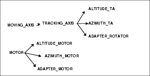
Inside a class definition we can put as attributes sub-points of a class. For example every instance of TRACKING_AXIS will have a motor.
By the way, quite often we are not able to really specify in the general class definition what specific type of sub-component will be instantiated. For example, different types of TRACKING_AXIS (i.e. ALTITUDE_TA, AZIMUTH_TA or ADAPTER_ROTATOR) will all have motors, but of different kinds.
This means that we must have the possibility to specify a generic class type for an attribute of the class, and to give more details about it at instance time or while defining sub-classes.
This procedure is what we call "overloading of class-type attributes":
Every class-type attribute of a class can be re-specified (overloaded) with another class-type, provided that it is a sub-class of the original one.
This is particularly useful when the general knowledge is enough to drive the device from outside (for example with commands from a workstation, using an access function or methods provided by a C++ access class), but must be considered internally also hardware constraint that depends from the specific instance.
In the TRACKING_AXIS example, we will have a hierarchy of classes defined in the library and inheriting from the base class. Every sub-class will overload the motor attribute with a proper specific motor type. Consider the sample hierarchy for MOVING_AXIS and MOTOR given in figure:
While defining a sub-class or an instance of a class that contains class-type attributes, the need of overloading some characteristics (typically the value) of an attribute inside the class-type attribute itself may arise. When there are more levels of nesting between sub-points, the attribute to be modified can be some levels down in the hierarchy of the instances.
In the last example, when we create an instance of the ALTITUDE_TA, we have to set the maximum allowed speed of the ALTITUDE_MOTOR that is "part-of" the altitude tracking axis. This value is stored in the "max" attribute of the motor's class-type attribute "speed" (it is of class ANALOG_VALUE): We have in this example three levels.
These situations are handled by specifying to the loader the path to reach the desired "sub-attribute". When such a definition is encountered, the loader checks that all the intermediate points exist and are of the correct types.
- Specialization of generic definitions helps to write code reusable in similar, but not identical situations
2.4.5 Scan system links
In the general VLT database architecture, the same physical object can be mapped both on the local database of a LCU and on the one of a Workstation. By the way, in most cases this last image is only a partial view of the LCU true object and not all the attributes will be mapped.
More over, the mapped attributes must actually contain the same values stored in the LCU image.
This means that values that can change with time must be kept aligned using the Scan System.
Since this necessity is usually known at database design time, the loader provides a way to define Scan Links.
In the ATTRIBUTE declaration it is possible to define scan links to attributes of other points using a simple syntax:
Consider for example an attribute that must contain a value polled from a given attribute of a point on a LCU every 2.0 seconds:
This, coupled with the ability to use preprocessor directives, makes easy to define in the same branch config file both the images of a point.
Consider the example of a device for which we have to monitor the temperature. The device will have its model on a LCU and an image on the control Workstation. The only attribute we need to monitor from the workstation is the value of the temperature, and this must be kept aligned via the Scan system.
- Different views of the same objects are kept aligned in an easy way, putting all the information in a unique and maintainable place.
2.4.6 Static and automatic attributes
Usually all the attributes defined in a class will contain values to represent the current status of a specific instance of the class. These values can be constant or can vary with time, but in any case they are used to specify the properties of that single specific instance.
Without any doubt the position of the motor specifies the current status of the device and can vary with time: at a given instant every motor has its own position.
At the same time the maximum rotation of the motor is a constant, but it is (at a first level of analysis) specific of THAT motor and other motors can have different values for that same attribute.
Each instance of the class must have its own personal copy of all these attributes (called "automatic") and by consequence the point put in the database will contain all these automatic attributes as inherited by all the ancestor classes.
It is easy to see that this is not the only case: some attributes describe characteristics common to all the instances of a class (called "static"). In this case, it does not make sense to have a private copy of the attribute in each instance.
If we consider a configuration in which we use 10 exactly identical motors, it becomes evident that the maximum rotation is a constant value common to all these 10 instances. The better solution in this case is to have a special sub-class of motor and to have a way of defining and accessing the maxRotation attribute as "static" for the whole class.
The loader recognize the following syntax to define "static" attributes:
From the user point of view, there is no difference in accessing static or automatic attributes with the services provided by the CCS, but the static ones are actually stored in a common place inside each local database and are actually shared by all the instances of the same class residing in that local database. Some characteristics of an attribute (like for example the value) can be overloaded also for static attributes: the new definition has to take place in a class definition and will affect all the instances of that class and descendents (but not ancestors).
A particular type of motor can work only if its temperature is under 80 degrees. This limiting temperature is logically defined as a static attribute of the class that describe that type of motor. In some special places it will be used and improved version of the motor. The only difference is that it can work up to 150 degrees. This improved motor is well described deriving a new class from the first one. It will only overload the value for the static parameter used to define the temperature.
2.5 Final database format
The loader tool processes a branch configuration file and produces the corresponding branch description in Rtap point config file format.
This description is compatible with both Workstation and LCU databases and can be loaded on any of them.
From the user's point of view, the Rtap database branch has a point per each point described in the configuration files. Class-type attributes are expanded as true points in the database and hierarchical structures are replicated with Rtap hierarchies of points.
Class dependencies are resolved expanding the point structure: the Rtap point will have its own copy of every (non static) attribute declared in all its anchestor classes, taking into account overloading of properties.his is exactly the same final structure that will have been carried out without the concept of classes: every single object must be specified completely in all its characteristics.
The centralized definition of common properties, that is inside the idea of class, leads to this result making easier the work of design, development and maintenance of the database.
The users of the database built by the loader mainly see a standard database and can interact with it using the standard LCU and Rtap utilities (such as RtapDbConfig and RtapPtDisplay). At the same time, all the standard CCS db functions and the Rtap Calculation Engine (on the workstation side) work properly. Interactive tools will be developed at a second time to replace the Rtap utilities and to make possible to navigate inside the database or to modify it using an Object Oriented approach. A short description of the function provided by these tools is given in the following paragraphs.
The following figure shows the general structure of the database; a box represents a hierarchy of points and the area grayed-out contains configuration sections used by the class implementation and normally not accessed by the user:
In order to implement these additional features, the database is integrated with ad-hoc attributes and points and CCS and Rtap Calculation Engine are to be extended to take advantage of these features, but they are usually not seen by the user:
· The database contains a special "class definition" branch where is described the class structure of the database: it contains one point per class, organized following the class inheritance hierarchy. The "class point" contains mainly the static attributes.
· All the classes are represented in the "class config" special point. The class numbers are automatically assigned by the loader.
· CCS read/write functions are modified in order to be able to navigate the class hierarchy and to locate the static attributes in a completely transparent way.
· A new Calculation Engine function implements the "class database view" to make it possible to write CE definitions using static attributes.
2.6 Design guidelines
please refer to document VLT Software Guidelines:
The provider of a software library or of an application accessing the database, has to define also one or more classes for the database points.
When the software or the application are configured, instances of these classes are created in the proper position in the database and all the attributes having non-default values are configured.
The VLT standard environment provides support for this development and installation phases, defining standard directories and standard makefile targets for database definitions (look at the man pages of the vltMakefile tool for more details).
Suppose that the user is developing a module in $MODROOT.
1. the software developer designs the classes for the database points. The class description files are placed in the $MODROOT/dbl directory and have extension .class. All the classes already designed and installed in $INTROOT or $VLTROOT are available.
2. The software developer writes some sample/test database branches using the new classes. He creates some .db files in the $MODROOT/dbl directory. These files have also to be installed in order to be used as templates.
3. Using the rules provided by the Makefiles, he can load a test database in $MODROOT/DB and check by hand what has been produced, load the points with the RTAP interactive tools (with the dbl tools when they will be available) or load the database on a running test environment.
4. when the development is complete, the database can be installed in the $INTROOT or $VLTROOT using the Makefile. This copies all the class definition files in the dbl subdirectory, so that they are available for everybody.
All these steps are controlled by the Makefile in the $MODROOT/src directory.
The list DBL_CLASSES contains the class files defined (without the .class extension).
The list DBL_BCF contains branch config files defined (without the .db extension).
The list DBL_LOAD contains the branch config files (without the .db extension) that must be loaded when the make db command is issued. It is a subset of DBL_BCF.
The target db will load the branch config files in $MODROOT/DB for testing, while the target install will install all the DBL_CLASS and DBL_BCF files in the integration or $VLTROOT area.
A true VLT environment is configured by the environment system manager, or by an automatic installation procedure, by editing the DATABASE.db file in the dbl directory of the environment.
This file must always be present and contains a list of include directives to build the database; among these are standard class definitions, template files and local .db files with the actual configuration of the database. It is always better to have in the DATABASE.db file only a list of includes and not directly point declarations.
The directory contains also a Makefile, usually empty.
The Makefiles's target db will load the whole database in the DB directory of the environment. The target clean will clean the whole DB directory.
Observe that if a file called DATABASE.db is present in the module's ../dbl directory, the command make db assumes automatically that this is the file to be loaded, no regard what is specified in the DBL_LOAD entry of the Makefile.
If the destination environment correspond to a LCU, it is only necessary to define for the Makefile the variable MAKE_VXWORKS. This will be passed as a #define to the dbl and can be used for conditional compilation.
The clean and db targets in a development $MODROOT/src directory will NOT clean the DB database destination directory. In particular this means that old database points, not any more described in the branch config files, are not removed automatically, but must be removed by hand. If the DB directory contains only points loaded with make db, it is suggested to modify this target's definition adding the cleaning of the DB directory as the first step. The same applies to the clean target.
In order to merge Point Config Files with a database description based on dbLoader's Branch Config Files it is necessary to follow the following steps:
· Modify the Makefile's target for db:
Add here a line to copy the PCF branch from the <mod>/dbl directory to the <mod>/DB directory, like for example:
· Modify the Makefile's target for install:
This procedure must copy the branch to some destination directory where it can be copied in the destination environment during configuration. It can be the $(xxxROOT)/dbl directory, where xxxROOT stands for VLTROOT or INTROOT
In an environment directory, during configuration:
· Put the Point Config Files' tree in the environment's directory
$VLTROOT/ENVIRONMENTS/<env>/dbl
Copying them from where they have been put by the module's install procedure.
· Modify the Makefile's target for db:
Add here a line to copy the PCF branch from the <mod>/dbl directory to the <mod>/DB directory, like for example:
2.7 Database loading on a running environment
The current release of dbl does not implement the options for directly loading databases on workstation's and lcu's running environments. A preliminary implementation of the loading on ws (-wl option) is available only internally to ESO.
This section contains some suggestions about the steps necessary to load by hand a database generated with dbl.
1. unload the database in one of the following ways (if it is necessary to restore current database values after having loaded the new database or if there are points not described in the .db files):
2.8 Caveats
This section contains solutions to common problems encountered when using the database loader.
It will be extended taking into account SPRs and frequently asked questions.
2.8.1 Limits of the preprocessor
The database loader support all but only the C language preprocessor (cpp) directives, as defined in Appendix A12 of the Kernighan & Ritchie[6].
This means that it is not a C interpreter and that it is not able to cope with C syntax that goes beyond what is defined for the C preprocessor.
Typical examples of not supported structures that one could be tempted to use are typedef and enum.
2.8.2 Sharing code with C and C++ programs
It is a good practice to put defines for symbols and values that must be shared between C or C++ code and database points in a common include file, used in every situation.
In order to do this, it is necessary to write an include file that contains only expressions that can be understood both by dbl and by the C compiler (typically #defines, see 2.8.1).
This can be placed in the ../include module's directory.
In order to make it visible for dbl, modify the Makefile's entry for DBL_FLAGS adding the C include directories to the search path, using the variable $(IPATH):
For conditional compilation, the macro MAKE_DBL is defined automatically by dbl at compile time. With this macro is possible to have separated dbl and C/C++ code in the same source file. For example :
For a piece of code to be use only by dbl sources.
2.8.3 The file DATABASE.db
If a file called DATABASE.db is present in the module's ../dbl directory, the command make db assumes automatically that this is the file to be loaded, no regard what is specified in the DBL_LOAD entry of the Makefile.
2.8.4 Loading big databases
Sometimes a database is too big to be loaded in one single step.
In this case it is enough to split the loading in two or more smaller sections.
· Issue the usual command make db. Make will issue a separate dbl command per every file in the DBL_LOAD section
2.8.5 Scan link configuration files
During database loading, scan-link definitions are currently only appended to the scan-link definition file, without checking if the same definition already exist in the file from a previous loading.
As a consequence, reloading several time the same files without cleaning the ../DB module's directory will result in scan-link definition files containing multiple times the same definitions.
2.8.6 Inheritance and overloaded classes
The database loader now supports the overloading of attributes in sub-points inside a class definition.
This remark replaces the corresponding section in the previous version of the manual and will be removed in the next release.
2.8.7 Duplicate alias names
When loading by hand on Rtap (with RtapDbConfig or RtapDbLoader) a database branch generated by dbl it is possible to get the error "duplicate alias" and the loading fails.
This happens when the same database is shared during development by more modules and is due to two facts:
As a consequence, when loading on a non empty database a new branch, it is likely to find that some aliases are already used there in other branches previously loaded.
The dbl command line option -a <num> can be used to overcome this problem defining the first alias number that must be used for the points of the current branch. The option can be set in the Makefile entry for DBL_FLAGS setting it in the following way:
As an alternative solution, since dbl keeps track of the aliases it has used, usually it is enough to issue again (one or more times) the "dbl" or "make db" command.Every time the database is regenerated, its points get higher alias values and will find soon and area not already used.
2.8.8 Multi-line macros definition
The standard preprocessor's splicing character `\' is just used to "pretty formatting" lines, that are anyway expanded on a single line.
As a consequence the following sample macro:
will expand on a single line in the following way:
That is probably not the desired result.
In order to overcome this problem, the preprocessor syntax has been extended adding the line break identifier "-;-". Every time this string is found in a macro definition, a new line character is inserted in the macro expansion.
The following sample macro will expand as a full point, whose name is given as a macro's argument, as desired:
2.8.9 Parser limitations
The dbl parser has some limitations due to its internal structure:
· No check can be performed on the value assigned to attributes. In particular no check can be performed on the values assigned to table and vector attributes. The check is performed by Rtap or by LCC during database loading in memory. This means that malformed expressions (misstype, wrong data types, wrong number of records or of elements, forgotten commas...) are often accepted by dbl or generate errors difficult to be interpreted by the user. If accepted, a proper error is anyway generated by Rtap at load time.
· In vector and table attribute definition and in attribute's value definition, the open round parenthesis "(" must be on the same line containing the attribute name or the "Value" keyword.
· Malformed expressions or unforeseen splitting of expressions between multiple lines can generate unexpected errors.
2.8.10 General branch properties
It is possible everywhere along the file to set the default values for general branch properties (3.1.6).
It is important to remember that these properties are in this way set from that point on as default values.
In particular, if a property is set inside an included file, it will be applied not only to the file itself, but from the inclusion point on in the rest of the main file and in all other eventually included files.
As a consequence general branch properties should never be used inside files that can be included by other files.
2.8.11 Parent class: BASE_CLASS or <base>?
As described in the reference section of this manual concerning class declaration (3.1.7), if a new class does not inherit from any special class, the parameter ParentClass should be set to BASE_CLASS; only in special cases, when no support for static attributes and no class support point are necessary, <base> can be used as parent class.
2.8.12 A class does not appear in the dbl class browser panels
The dbl class browser shows the hierarchy of all classes derived from BASE_CLASS. If a class does not have BASE_CLASS as an ancestor and is a sub class of <base>, it does not appear in the dbl class browser.
2.8.13 Wrong expansion for a macro appended to a string terminated by interpuntion character
As described in spr 960089, whenever a macro is appended to a string terminated by `:' or by `.', the pre-processor adds a space.
The result of this expansion is :Appl_data: ccdUvR instead of :Appl_data:ccdUvR
This is a limitation of DBL and is due to the implementation of the underlying CPP preprocessor.
2.9 Interactive database tools
The interactive database tools distributed within the Rtap package can be used with the database created by the loader, but only to browse the database structure (modifications will easily put it in an inconsistent status). VLT engineering user interface tools ([4],[5]) can be used to access database points and change their values.
The only tool developed up to now and available as a prototype is a class browser. Other tools, such as a database editor to replace RtapDbConfig with a better user interface and class support, are under investigation.
2.9.1 Class Browser
This tool is an interactive user interface to manipulate the classes' definitions and the classes' hierachies, similar in concepts to the class browsers available for all the object oriented programming languages.1
It acts on the static information saved in the class description files and does not use any run time information from the on-line database.
It is useful to define and edit new classes, but, from the user's point of view, it is first of all a source of documentation. If a class library is well documented, an interactive graphical representation of the hierarchy is much more useful in order to collect information about class usage.
It will contain also functions to print class documentation suitable for insertion in official VLT documents.
The interaction with the browser is driven by the concept of "selected class". It is possible to set the "selected class" in several ways. When a class is selected, it appears on a status line and menus and
all buttons bindings acts on it.
The browser is divided in some windows. Some of them can be switched ON/OFF. Whenever the "selected class" is changed all relevant windows are automatically updated.
Two TREE windows are provided to show the representation of the class hierarchy and the point hierarchy for the points contained in classes with structured attributes.
An object selected with the left mouse button becomes the "selected class". It is possible to hide subbranches of the trees clicking on a tree node:
- If I am looking at the full tree and I middle click on a node, the children are hidden. Dead branches shows that there are hidden children.
- If I right click on the root of what I am viewing, its parent point appears, with dead branches for the not shouwn children.
A LIST window will contain the list of defined classes. It is possible to select what is shown using wildcard expressions (e.g AH* will show only all the classes starting with the string AH). A list element selected with the left mouse button becomes the "selected class".
A DEFINITION window will contains the definition of the currently selected class. A class is selected by clicking it on a TREE or LIST window (its name is shown in a status line). A list element (for example a class type attribute) selected with the left mouse button becomes the "selected class".
The definition window contains the definition for its data members (type, name, initial value) choosing from a menu one of the following display strategies:
Table's and vector's records could be shown on a separate window when requested (otherwise a clean formatting would be difficult).
It is possible to freeze a DEFINITION window and open a new one, in order to view at the same time the definitions for more than one class.
A MAN PAGE window contains the man page of the currently selected class, formatting from its source file standard VLT header. It is possible to freeze a MAN PAGE window and open a new one, in order to view at the same time the man page for more than one class.
These actions are defined for the class hierarchy TREE window menus:
Print To print a file with a description of the currently selected branch (a visible in the TREE window).
Select Bring up an input window to allow the user to define the "selected class" via an input prompt
These actions are defined for the TREE window displaying the structured attributes for the "selected class":
Print To print a file with a description of the currently selected branch (a visible in the TREE window). It must be used to prepare documentation to be inserted in the manuals.
Select Bring up an input window to allow the user to define the "selected class" via an input prompt
These actions are defined for the menu on the DEFINITION window
2.10 Sample definition files
This chapter contains some complete examples of "branch configuration file" and of "class definition files". For some of this examples it is given also the corresponding structure in term of standard "Rtap point configuration files", to make easy the check of the differences between the two approaches and to put in evidence the advantages introduced by the concept of class.
2.10.1 Sample database for the motor library
The interrelations between the classes defined in this example can be summarized in the following diagram, where the "is a" relation, (inheritance dependence between a class and a sub-class) and the "part of" relation (an instance of a class is a member of another class) are put in evidence.

As a consequence, every time we define an instance of class STD_MOTOR_1 we get the following Rtap database structure:

2.10.2 The RANGE_VALUE class hierarchy
In the following example we give a simplified description of the RANGE_VALUE class hierarchy. These classes are given in the VLT class library.
Their purpose is to give a standard way to treat attributes whose values have to be checked against a range of allowed choices.
An example of the use of these classes has been given in paragraph 2.4.3.
The diagram shows the interrelations between the defined classes. The classes enclosed in a box are expanded in the example.
// A set of C functions or C++ access classes must be provided
// for every class in order to implement access methods.
2.10.3 Rewriting an example of Point Configuration File
The following example is just the rewriting, using the new syntax, of the sample Point Configuration File given at page 21 of the LCU Common Software User Manual[5].
Here we do not make any use of the class concept, but we just translate the point description: the new format is much more readable and compact.
// * sample "Point Config File
// *************************************************************
// The point has no class support
ATTRIBUTE bytes8 airUnits "m^3/sec"
ATTRIBUTE float waterUse 8.0938139
ATTRIBUTE Bytes16 wsupplyCondition "Water supply on"
ATTRIBUTE Table breakerDetail(10,
uint8 control, uint8 status, bytes8 condition,
bytes48 location, float rating)
Value ( (0, 0, "", "Control Room", 22.0),
(0, 0, "", "Computer Room", 18.5),
(0, 0, "", "Storage Room", 15.3),
(1, 1, "", "Enclosure", 10.42),
(1, 1, "", "Nasmyth A Instrument", 11.38),
(0, 0, "", "Nasmyth B Instrument", 9.67),
(0, 0, "", "Cassegrain Cage", 12.73),
(1, 1, "", "Coude Room", 14.81),
(1, 1, "", "Hydraulic Plant", 19.2),
(1, 1, "", "Air Conditioning", 5.27)
ATTRIBUTE Vector dutyAlarmVector(9, uint)
Value (1, 43, 46, 24, 196, 0, 2, 75, 56)
ATTRIBUTE double rainIn 0.5392742753102887
ATTRIBUTE uint32 dbfCategories 4294967295
1A prototype version of the dblcb tool is part of the current release. Look in the release notes for limitations and known problems
|
Quadralay Corporation http://www.webworks.com Voice: (512) 719-3399 Fax: (512) 719-3606 sales@webworks.com |