All raw data (except for BIAS and DARK frames) have two binary tables in
addition to HDU#1 hosting the pixels: HDU#2 is the ozpoz table, HDU#3 is the
fibre table.
The OzPoz table relates objects on the sky and fibre buttons in Ozpoz. It is
partly defined by the user in the Target Setup File. Check out the FPOSS
manual for more information.
Column
Content
Comment
Col 1
OBJECT
Identification (from Target Setup File, col 1)
Col 2
RA
Right Ascension (from Target Setup File, col 2)
Col 3
DEC
Declination (from Target Setup File, col 3)
Col 4
R
Button R (polar coordinate) position (microns)
Col 5
R_ERROR
Error in R (microns)
Col 6
THETA
Button Theta position on plate (radians)
Col 7
THETA_ERROR
Error in Theta (radians)
Col 8
TYPE
Object type (M=Medusa science, I=IFU science, S=sky etc.)
Col 9
BUTTON
OzPoz button number
Col 10
PRIO
Object priority (from Target Setup File, col 5)
Col 11
ORIENT
Button orientation
Col 12
IN_TOL
T or F if positioned or not within tolerance (40 microns = 0.08")
Col 13
MAGNITUDE
Target Magnitude (from Target Setup File, col 6; SCIENCE only)
The second binary table attached to raw files is the Fibre Table. It relates the fibre buttons on
Ozpoz and the fibre positions in the slits, and also includes lab-measured
fibre transmission values. This table is static and is maintained by the
Observatory.
The columns have the following content:
Column
Content
Comment
Col 1
SLIT
slit name and plate (Medusa1, Medusa2, IFU1, IFU2, Argus)
Col 2
FPS
Progressive position number of fibre in the slit
Col 3
SSN
Subslit number
Col 4
PSSN
Fibre position in the subslit
Col 5
RETRACTOR
Serial number of the retractor
Col 6
BN
Serial number of the button used in the retractor
Col 7
FBN
Serial Number of the Fibre used for the button
Col 8
RP
Retractor position on the plate. This number corresponds to the fibre number used e.g. in FPOSS (target setup file). All even numbers are Medusa fibres.
Cols 9-17
wave
Fibre Transmission values as measured in the lab (as percentage). Each column has a different wavelength.
Col 18
X
X position of the fibre in the reconstructed image matrix
Col 19
Y
Y position of the fibre in the reconstructed image matrix
Col 20
FPD
fibre position on the detector; for Medusa and IFU identical to FPS, for Argus the order is reversed.
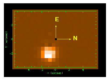
The ARGUS image reconstruction using the X and Y columns for the table
gives the image in the standard NE orientation on the sky. If the ARGUS
position angle was 0 (ARGPOSAN = 0), N is along the X axis and E along the Y
axis. The position angle is counted N to E.
This table is attached to each pipeline product, as HDU#2. It combines
information from the ozpoz and the fibre tables, and includes added
information:
Column
Content
taken from
Comment
Col 1
INDEX
pipeline
index of the fibre signal as found by the pipeline
Col 2
FPS
fibre
Progressive position number of fibre in the slit
Col 3
SSN
fibre
Subslit number
Col 4
PSSN
fibre
Fibre position in the subslit
Col 5
RP
fibre
Retractor position on the plate. This number corresponds to the fibre number used e.g. in FPOSS. All even numbers are Medusa fibres.
[Col 6]
[X]
fibre
X position of the fibre in the reconstructed image matrix [IFU and Argus only]
[Col 7]
[Y]
fibre
Y position of the fibre in the reconstructed image matrix [IFU and Argus only]
Col 8
RETRACTOR
fibre
Serial number of the retractor
Col 9
FPD
fibre
fibre position on the detector; for Medusa and IFU identical to FPS, for Argus the order is reversed.
Col 10
OBJECT
ozpoz
Identification (from Target Setup File, col 1)
Col 11
R
ozpoz
Button R (polar coordinate) position (microns)
Col 12
THETA
ozpoz
Button Theta position on plate (radians)
Col 13
ORIENT
ozpoz
Button orientation
Col 14
TYPE
ozpoz
Object Type
Col 15
RA
ozpoz
Right Ascension (from Target Setup File, col 2)
Col 16
DEC
ozpoz
Declination (from Target Setup File, col 3)
Col 17
MAGNITUDE
ozpoz
Target Magnitude (from Target Setup File, col 6; SCIENCE only)
OBJECT,SimCal data only: differential wavelength shifts, applied for differential correction and obtained by the pipeline from the SimCal fibres
Col 20
GCORR
pipeline
OBJECT,SimCal data only: geocentric correction to be applied (in km/s)
Col 21
HCORR
pipeline
like above, heliocentric correction
Col 22
BCORR
pipeline
like above, barycentric correction
The INDEX counts the pipeline-detected fibres. It will always increment by
one. The FPS represents the physical index of the fibres. As long as it
increments along with INDEX, this means that all fibres (up to the present
INDEX have been allocated and extracted. An increment by more than 1 means
that at least one fibre has given no signal, either because it could not be
allocated (fibre broken), or has not been allocated by the user, or had a
signal too low for the pipeline to detect. The last possibility will actually
not happen since fibre signal localization is always done on flat field data,
and if there a fibre gives too low a signal, it can be considered as not
operational.
The number of columns in the product files corresponds to the maximum INDEX.
There are no columns for fibres with no signal.
 Fibre table