OmegaCAM ISSUES and PROBLEMS |
This page describes all Instrumental, Quality Control, and Pipeline Issues that have arisen since the beginning of OmegaCAM operations on Oct., 15, 2012.
2012-05-01 to 2012-06-04: Sporadic variations and striping in detector ESO_CCD_82 |
Since the beginning of operations, detector ESO_CCD_82 has shown gain variations of a few percent. This instability seems to have worsened beginning from 2012-05-01 (P89). At its worst, detector #82 can show strong horizontal striping. There does not appear to be a pattern to this misbehaviour and it appears and disappears within short frames of time.
This has been solved by replacing a video board within OmegaCAM, but resulted in a sharp increase in the read-out noise and bias levels of the four detectors adjacent to #82.
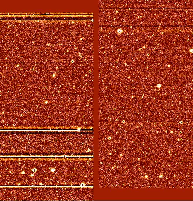
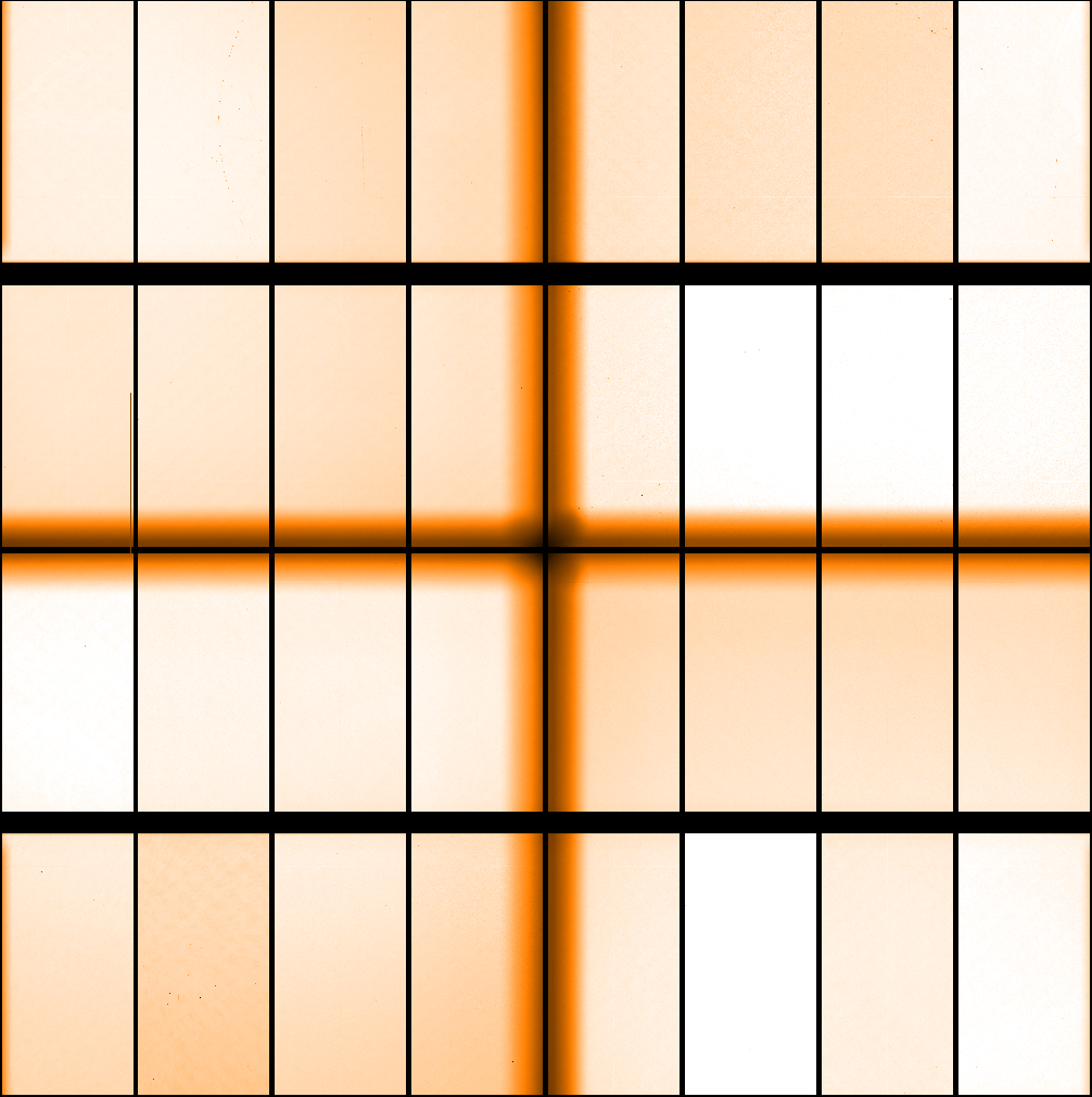
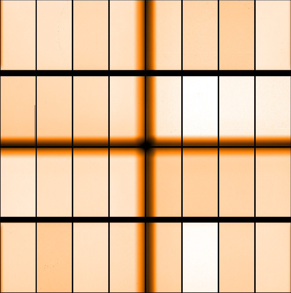
This frame shows the instability that sometimes appears in detector ESO_CCD_82. This is the combination of a two exposure science OFFSET, with the left-hand exposure showing extensive striping, while the right-hand image, obtained only minutes later, showing much less pronounced striping.
 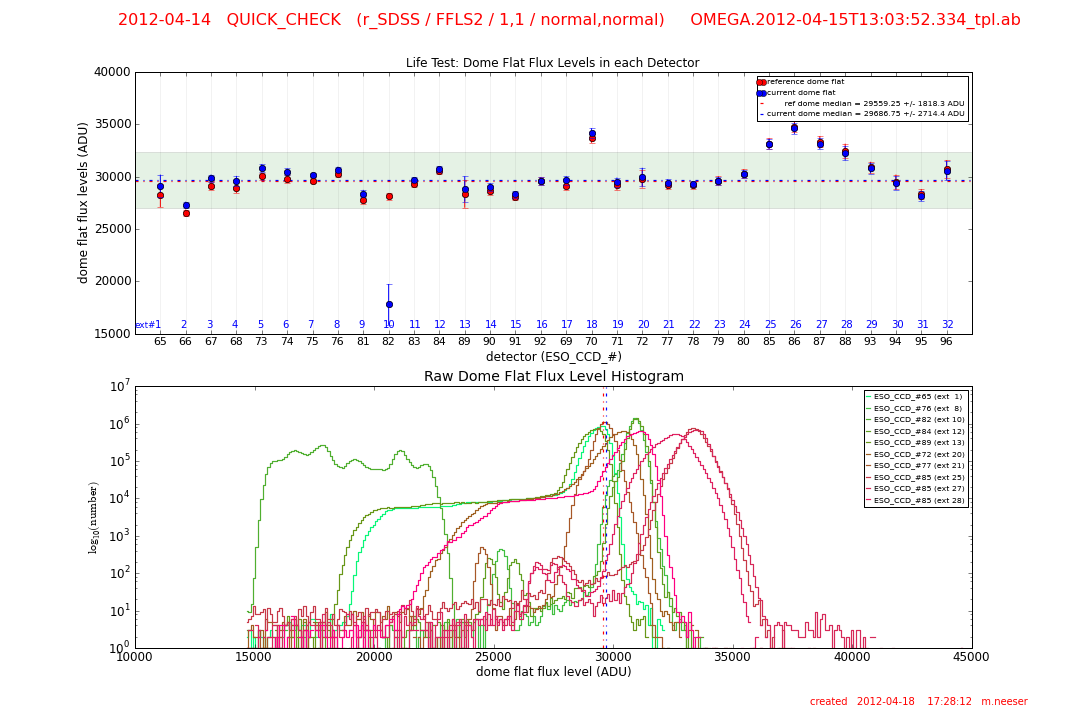
Alternatively, the striping can be more extreme with differing response levels. This is best seen in a quick-check dome flat (left panel), and in the resulting quality control flux level check (right panel). Here, the depressed flux response (current values are blue, reference frame values are red) of detector #82 is obvious).
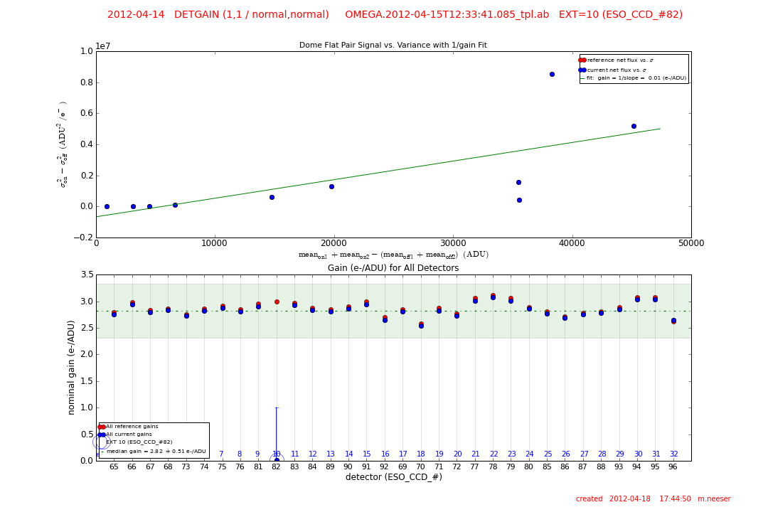
When this effect occurs in the gain/linearity template, the gain computed for detector #82 will be below its reference value (red points), and in the most extreme cases the gain will be zero.
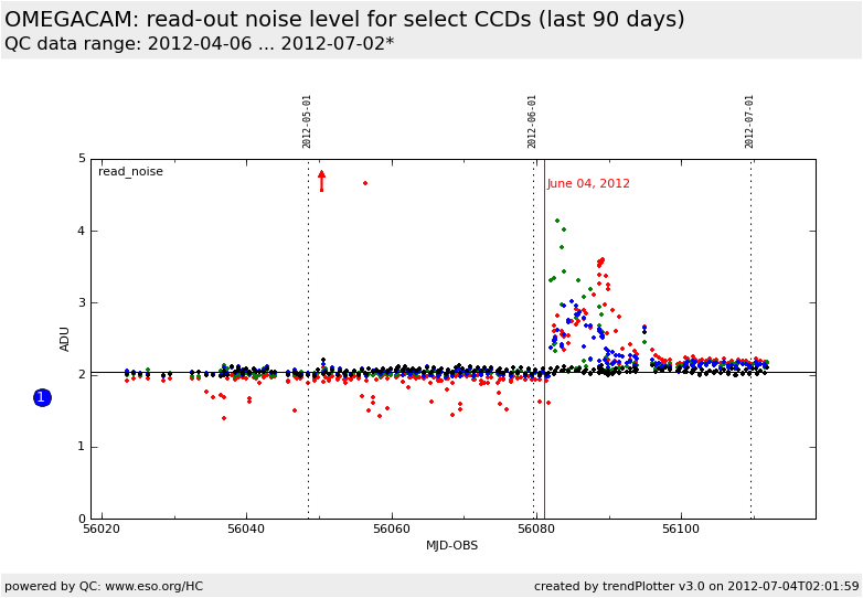
With the replacement of the video board came an increase in the read-noise of the four detectors around #82. As can be seen in the above plot, this settled down after about two weeks.
Detector #82 is monitored in all health check plots that include the parameters from each individual detector, but a detailed monitoring of CCD #82 is also done for both its bias level and its flux response shown in these links (in each case CCD #82 is directly compared to more stable detectors):
raw bias level (detector #82)
read-out noise (detector #82)
dome flat flux (detector #82)
2011-10-15 to Present: Vignetting of the composite filters |
A number of OmegaCAM filters consist of four segments (each covering 8 detectors). As such, they are have a central cross-shaped support structure. This creates a vignetting effect that will be visible in 20 detectors which is significantly larger than the gaps present between adjacent CCD's. This should be considered when chosing a dither pattern.
The affected filters are:
B_JOHN
V_JOHN
H_ALPHA
NB_659
NB_852
   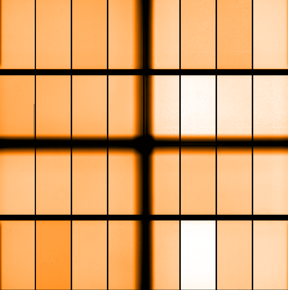
The vignetting present in the composite filters (from the left): B_JOHN, V_JOHN, H_ALPHA, NB_659.
A conservative accounting for the total size of the vignetted area can be summarized as:
| Filter |
North/South Vignetting |
East/West Vignetting |
| B_JOHN |
1405 pixels (300 arcsec) |
1405 pixels (300 arcsec) |
| V_JOHN |
1430 pixels (306 arcsec) |
1410 pixels (302 arcsec) |
| H_ALPHA |
1418 pixels (305 arcsec) |
1407 pixels (302 arcsec) |
| NB_659 |
1418 pixels (305 arcsec) |
1407 pixels (302 arcsec) |
2011-10-15 to Present: Polar field composite filter (u_g_r_i_SDSS) has no flux in dome flats |
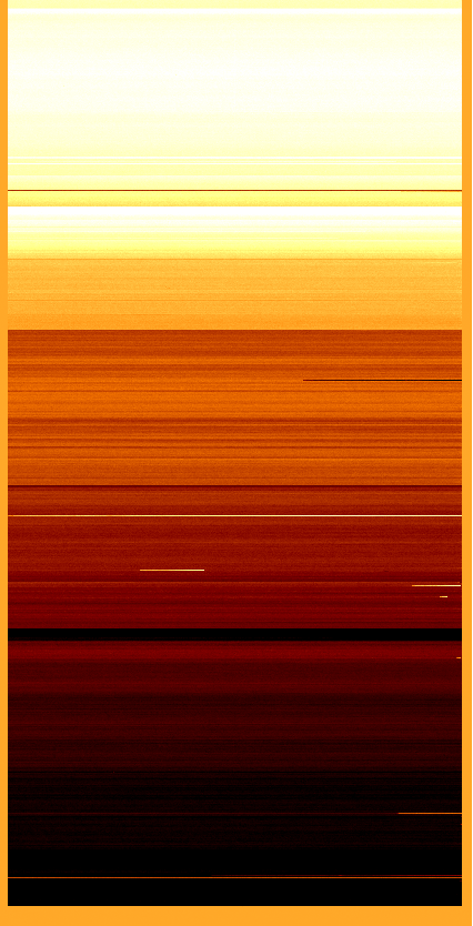
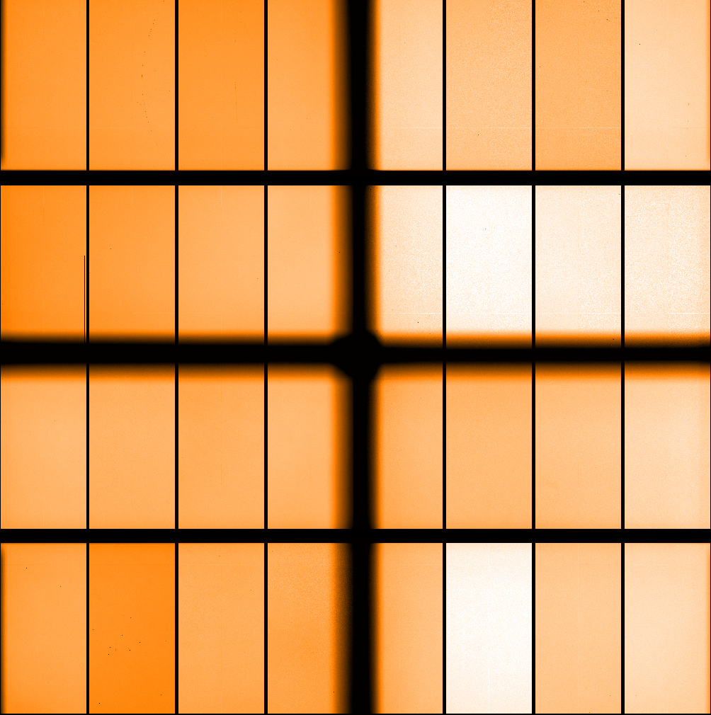
Owing to a relatively red lamp spectrum, and the sensitivity of the g, r, and i segments, the dome flats of the u_g_r_i_SDSS composite polar field filter have virtually zero flux in the u-band quadrant. It therefore makes sense to only use the u_g_r_i_SDSS twilight flats to processes the data taken with this filter.
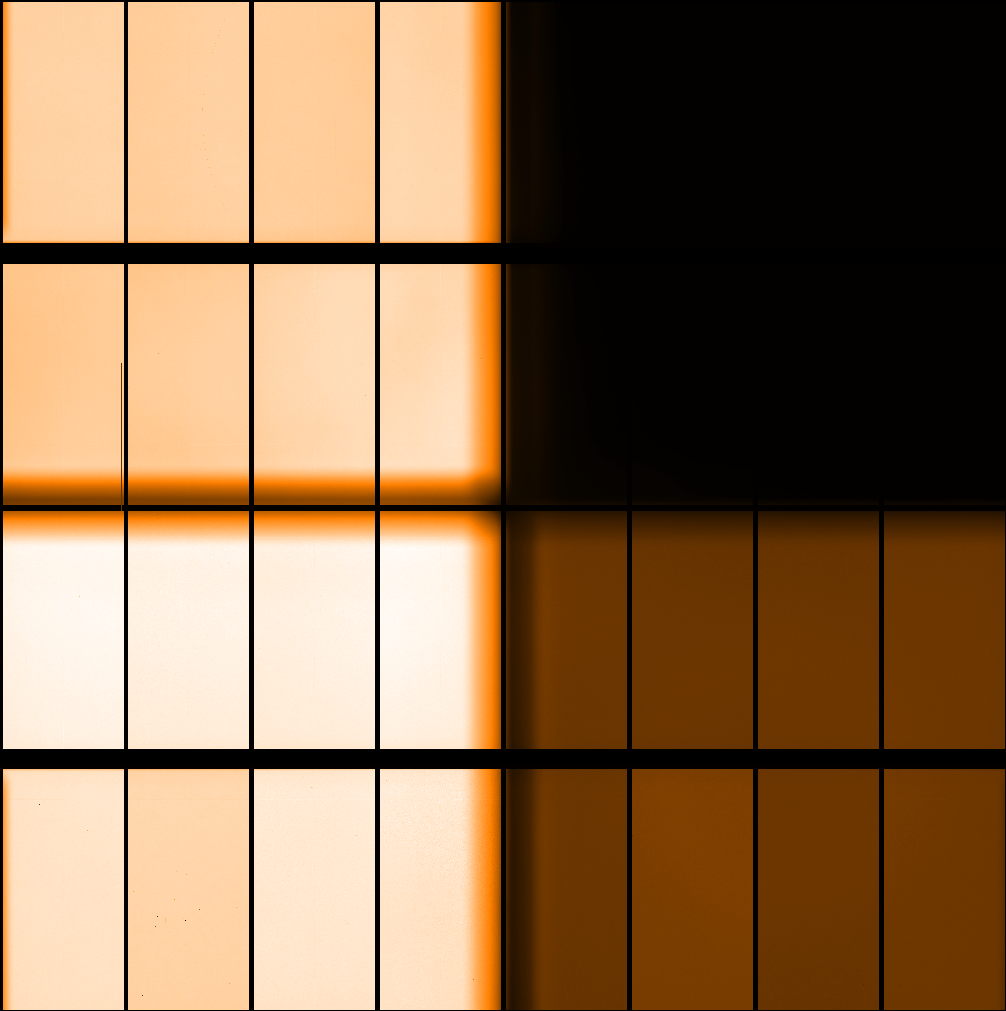
A raw dome flat with the u_g_r_i_SDSS filter. The insufficient flux level of the u-band quadrant (top right) is evident. The flux levels are typically
| Filter |
Typical flux level (ADU) |
| r' |
44,000 - 48,000 |
| i' |
50,000 - 55,000 |
| g' |
12,000 - 14,000 |
| u' |
300 - 800 |
2011-08-01 to 2011-10-20: Field rotation jumps (now solved!) |
From the beginning of OmegaCAM/VST commissioning to
mid October, 2011 there appeared to be random jumps in the rotation of the field of as much as 2 degrees. This problem is now solved, and has not affected data post October 20, 2011.
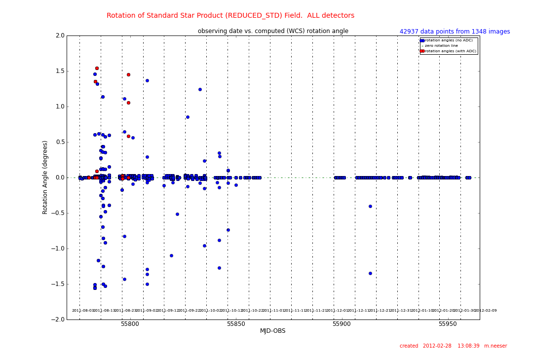
A plot of the rotation angle (in degrees) vs. date for secondary standard fields taken between August and October 2011. The random
jumps in field rotation angle are apparent up to the end of October.
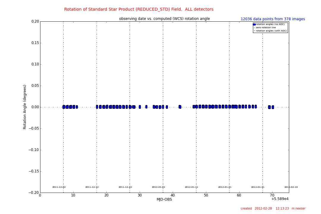
A zoom of the above plot of the rotation angle (in degrees) vs. date for secondary standard fields taken between December 2011 and
February 2012. The absence of a random jumps in field rotation angle shows that this issue has been solved.
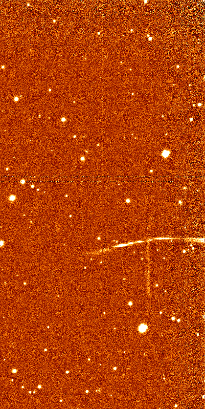
Commissioning to Present: Fringing |
The blue-sensitive EEV detectors of OmegaCAM are very susceptible to fringing. This is evident in both the i'_SDSS and, in particular, the z'_SDSS filters. When the data is observed under good atmospheric conditions (photometric -> clear), the fringing is relatively stable and can be corrected by creating science frame-based superflats and scaling and subtracting these from the science images.
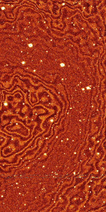
A particularly strong example of z-band fringing visible on a single OmegaCAM detector.
Commissioning to Present: Cross-Talk |
Detector cross-talk (the situation whereby the signal from one detector can find its way into a neighbouring detector) can exist for OmegaCAM CCD's numbered ESO_CCD_94, #95, and #96. It manifests itself most clearly by bright sources in detector #95 being mirrored as inverted (or negative) sources in detector #96. The sources need not be saturated to create a cross-talk image in a neighbouring detector. The cross-talk image is usually less than or equal to 0.4% the brightness of its parent source.
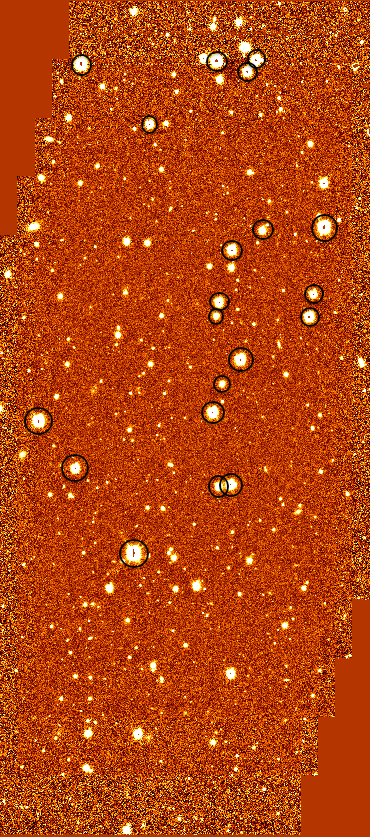 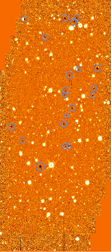
ESO_CCD_95 and ESO_CCD_96
Evidence of cross-talk: Bright sources (shown with black circles) in detector #95 are mirrored as negative sources (shown with blue circles) in the neighbouring detector #96.
Commissioning to Present: Ghosting Around Bright Sources |
Multiple reflections in the internal optics of OmegaCAM can produce complex image rings and ghosts near very bright sources. It is important to note that reflections can be visible even if the source star is placed in the gap between detectors.
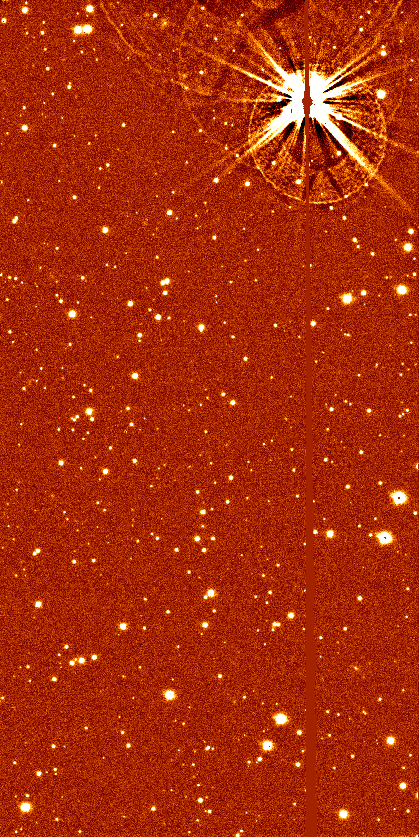
Internal reflections surrounding a very bright star in a single detector image obtained with the V_JOHN filter.
More insidious are the internal reflections that result from a bright star that is off the frame, yet produces reflective structures within a given detector.
Commissioning to Present: Structure in Bias Frames |
Two OmegaCAM detectors (ESO_CCD_#68 and #90) show a centrally elevated structure in their bias frames. This structure, however, remains constant with the underlying bias level and can be easily corrected.
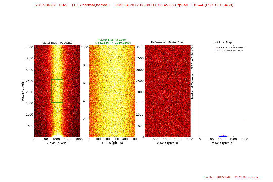 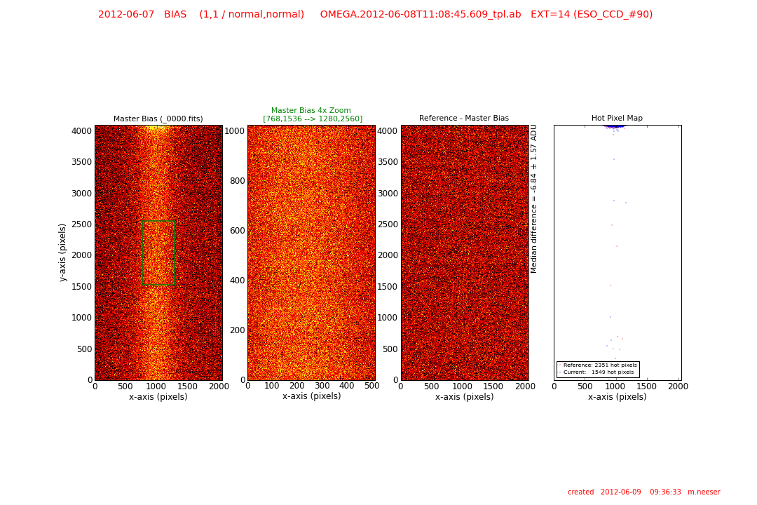
QC reports for the bias frames of detectors #68 (left panel) and #90 (right panel). Each shows the master bias frame (left) with its central ridge structure and the difference frame (reference - current master bias) showing the stability of this structure (third frame from left). The number of hot pixels are elevated at the brightest part of the central ridge structure (last frame in each panel).
|
