Creating an FGF Application
Since the main purpose of the FGF is to provide a ‘simple and easy way’ to create a dedicated frame grabber application for specific camera solutions, a template is provided by the FGF package: “ifw-fgf/fgf/template/fgf-dvc”.
A tool is provided to create the target FGF Application in the desirable location from the template: “fgfNewApp”.
It shall be mentioned here that, the tool and template only creates the rough framework which can be used as starting point for the development of the new frame grabber. The generated frame grabber module can be compiled and executed, though.
The present template is based on the FGF Simulator, in order to generate an already running example. This might make it easier to start implementing the new frame grabber application, but adapting the new instance of the simulator generated from the template, step by step.
Noticeable is that the FGF template itself is built and installed with the FGF package (executable: “fgfDvc”).
Structure of the Template
In this section, the content of the template is described, with an indication of which files the user will have to update.
The following shows the directory structure of the template:
fgf-dvc/
├── adapter
│   ├── src
│   │   ├── $commAdaptor.cpp
│   │   └── include
│   │       └── sbss
│   │           └── fgf
│   │               └── dvc
│   │                   └── $commAdapter.hpp
│   └── #wscript
├── server
│   ├── resource
│   │   └── config
│   │       └── sbss
│   │           └── fgf
│   │               └── dvc
│   │                   └── $fgNodeSet.yaml
│   ├── src
│   │   └── main.cpp
│   └── #wscript
├── ualib
│   ├── src
│   │   ├── callbacks.cpp
│   │   ├── include
│   │   │   └── sbss
│   │   │       └── fgf
│   │   │           └── dvc
│   │   │               ├── callbacks.hpp
│   │   │               └── nodeset.hpp
│   │   └── nodeset.cpp
│   └── #wscript
└── #wscript
The name “dvc” will be replaced by the name of the camera/device for which the new frame grabber is dedicated. Likewise the name “sbss” will be replaced by the name of the subsystem within the instrument project, to which the frame grabber logically belongs.
The files that the user will have to adapt are marked with “$”. The files that the user may have to adapter, with “#”.
The elements in the diretory tree are:
fgf-dvc: The top-level directory of the new frame grabber application.
fgf-dvc/adapter: This contains the code for the communication adapter needed for the specific camera.
fgf-dvc/server: The frame grabber deployment module, generating the executable via the “main.cpp” file. This shall normally not be modified by the user, but could be modified to accommodate for specific needs. The “fgNodeSet.yaml” contains the definition of the OPC UA namespace to be deployed in the frame grabber; this is normally the ENVision OPC UA set of nodes, possibly aggregated with a set of specific nodes, needed for a specific camera, e.g. for telemetry monitoring purposes.
fgf-dvc/ualib: Contains the code, which is invoked by the frame grabber to create the OPC UA namespace (done via the “open62541” SDK). The source files under “ualib” are generated from the “fgNodeSet.yaml” definition, and shall not be touched by the user.
Prerequisites
The IFW FGF project must be installed on the node where the new FGF Application is being developed. In particular, access to the FGF Template, contained in “ifw-fgf/fgf/template/fgf-dvc”, must be granted.
Steps to Generate the New Frame Grabber Application Module
The FGF Application generator tool provided by the FGF package can create the new FGF project in two contexts:
As a standalone WAF project.
By adding the new FGF project inside an existing WAF build structure.
It shall be mentioned, that if the new FGF Application depends on third party/proprietary SDKs, it must be created as a standalone project, which can be build and installed on the FGF dedicated node, where the given SDKs are available. I.e., it is not permissable to add such an FGF Application, e.g. in the instrument source tree, making it depending on third party libraries.
The following instructions examplifies creating a new standalone FGF Application.
These guidelines are meant as rough indications, and the user is requested to adapt to the actual environment in which the new frame grabber is located.
The procedure to create a new frame grabber application are as follows:
Enter the location where the new frame grabber should be added (e.g.):
$ cd ~/workspace
Invoke the FGF Frame Grabber Generator Tool with the “standalone option” (-s), referencing to the provided template:
$ fgfNewApp -t ~/workspace/ELT/Git/ifw-fgf/fgf/template/fgf-dvc/ -y subsys -d mycam -s
Arguments:
Template Location: |/home/jknudstr/workspace/ELT/Git/ifw-fgf/fgf/template/fgf-dvc/|
Standalone:        |True|
Subsystem:         |subsys|
Device:            |mycam|
Compile the new frame grabber (note: if the new FGF Application is added in an existing WAF build structure, it is necessary to invoke “waf configure” at the top-level of the project):
$ cd fgf-mycam
$ waf configure install
Execute the frame grabber application generated and verify that it is working properly:
$ fgfMycam -h
   Options:
   -h [ --help ]                     Print help messages
   -a [ --address ] arg (=127.0.0.1) RTMS source IP address
   -p [ --port ] arg (=59000)        Network port
   -n [ --netif ] arg                Network interface to be used
   -s [ --fits-file ] arg            FITS filename to be used for the image
                                       stream
   -f [ --log-prop-file ] arg        Log property filename
   -u [ --uaport ] arg (=4840)       OPCUA server port
   -l [ --log-level ] arg (=ERROR)   Log level: ERROR, INFO, DEBUG, TRACE
--list-loggers                    List defined loggers and exit
Launch the application:
$ fgfMycam -a 127.0.0.1 -p 59000 -n 127.0.0.1 -s /elt/ifw/resource/image/ifw/ccf/control/test_naxis3_1_512_int16.fits -l INFO --uaport 7777
INFO - Starting application...
INFO - Cube number of planes: 10
INFO - Image BPP: 2
INFO - Image width: 512
INFO - Image height: 512
[2025-02-11 17:48:31.768 (UTC+0000)] info/eventloop     Starting the EventLoop
INFO - Acquisition Thread started
INFO - Acquisition waiting...
[2025-02-11 17:48:31.768 (UTC+0000)] warn/server        AccessControl: Unconfigured AccessControl. Users have all permissions.
. . .
A FITS image cube is required as input for the generated dummy application. If “ifw-ccf” is installed on the host, the above listed FITS cube should be available, either in the “INTROOT” or in “/elt”.
Note also that the new frame grabber application is started with the option “–uaport” with which a specific port number can be assigned to the OPC UA server.
On a host where UA Expert, or another OPC UA client is available, start this up and connect to the new frame grabber (here UA Expert is used):
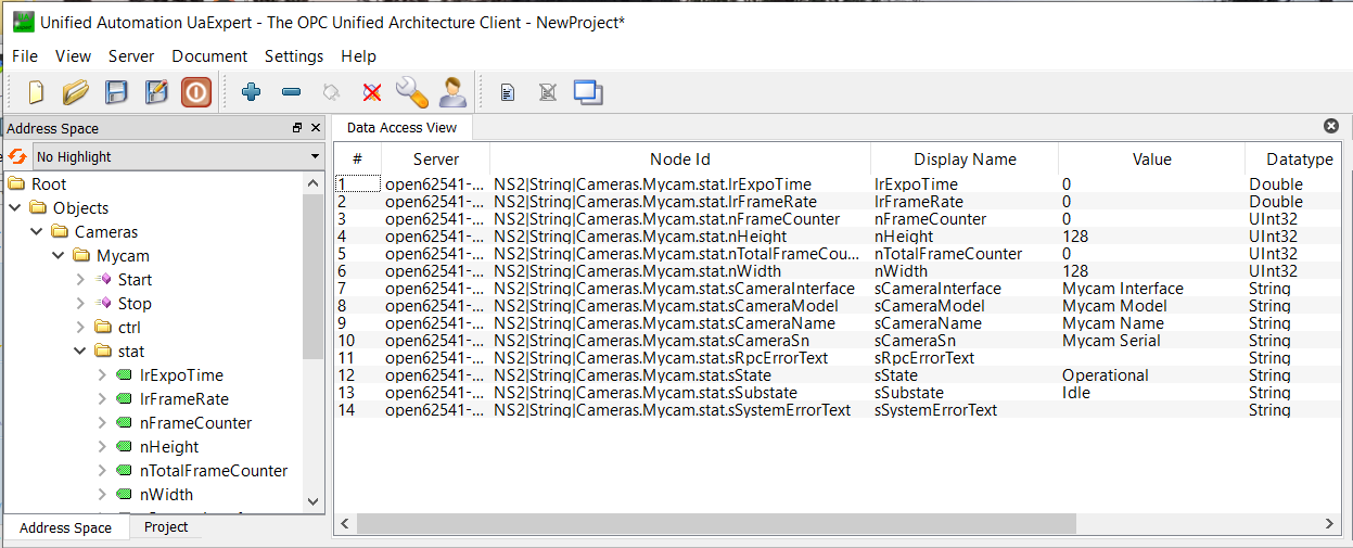
Execute the “Start” method and observe that the frame grabber enters “Acquiring”, which means it starts publishing images via RTMS:
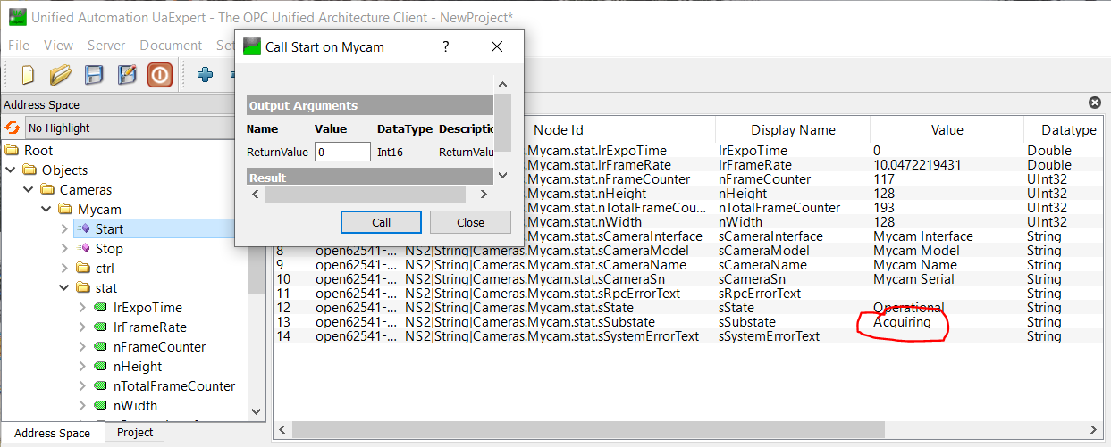
At this point, it could now be attempted to receive the images published via RTMS with an RTMS subscriber, e.g. “rtmstoolsRtms2Ddt”; see RTMS Tools Test Scenario: Test Scenario/Example 2: FGF Simulator + RTMS Tools - RTMS to DDT Gateway.
To generate a new FGF frame grabber project and add it in an existing WAF build structure, simply invoke the FGF project creating tools as follows in the location where it is desirable to add the new FGF project:
$ fgfNewApp -t ~/workspace/ELT/Git/ifw-fgf/fgf/template/fgf-dvc/ -y mysubsys -d mycam
Afterwards the “wscript” files of the existing WAF build structure must be updated manually to reflect the new branch added.
Note, that template is implemented to be added in a structure like this “<project>/<subsys>/fgf/”, i.e., under the “fgf” directory. If it is the intention to add it in another structure/location, it may be necessary to adjust the “wscript” files inside the generated FGF Application project structure.
A small WAF project is provided, to show how to add an FGF application WAF build structure into an existing WAF project: “ifw-fgf/fgf/template/fgf-demo-prj”:
fgf-demo-prj/
├── mysubsys
│   ├── fgf
│   │   ├── $mycam
│   │   │   ├── adapter
│   │   │   │   ├── src
│   │   │   │   │   ├── commAdaptor.cpp
│   │   │   │   │   └── include
│   │   │   │   │       └── mysubsys
│   │   │   │   │           └── fgf
│   │   │   │   │               └── mycam
│   │   │   │   │                   └── commAdapter.hpp
│   │   │   │   └── wscript
│   │   │   ├── server
│   │   │   │   ├── resource
│   │   │   │   │   └── config
│   │   │   │   │       └── mysubsys
│   │   │   │   │           └── fgf
│   │   │   │   │               └── mycam
│   │   │   │   │                   └── fgNodeSet.yaml
│   │   │   │   ├── src
│   │   │   │   │   └── main.cpp
│   │   │   │   └── wscript
│   │   │   ├── ualib
│   │   │   │   ├── src
│   │   │   │   │   ├── callbacks.cpp
│   │   │   │   │   ├── include
│   │   │   │   │   │   └── mysubsys
│   │   │   │   │   │       └── fgf
│   │   │   │   │   │           └── mycam
│   │   │   │   │   │               ├── callbacks.hpp
│   │   │   │   │   │               └── nodeset.hpp
│   │   │   │   │   └── nodeset.cpp
│   │   │   │   └── wscript
│   │   │   └── wscript
│   │   └── wscript
│   └── wscript
└── wscript
It shows how to prepare the “wscript” files etc.
The new FGF Application structure is located under this path: “fgf-demo-prj/mysubsys/fgf/mycam”.
Defining & Generating the OPC UA Namespace
After having generated the new FGF frame grabber application project from the templates, the OPC UA namespace definition can be found in this location “fgf-<device>/server/resource/config/subsys/fgf/mycam/fgNodeSet.yaml” (refer to the “Overview” chapter for a description of the format).
The nodes defined in the node set YAML file are the mandatory nodes for the ENVision Protocol; do not change these existing nodes. Also, do not change the existing hierachy in the namespace definition. I.e., “Cameras.Mycam.stat” and “Cameras.Mycam.ctrl” shall remain as they are. Also do not alter the location or name of the “Start/Stop” methods.
It is allowed adding additional nodes under “Cameras.Mycam.stat” and “Cameras.Mycam.ctrl”, adding new ‘container’ nodes and to add more methods. Support for these will have to be added in the FGF Adapter.
A typical use case for adding new nodes, could be to add parameters defined in the camera firmware, to be read for the purpose of telemetry, or to add new control (“ctrl”) nodes if required to control the camera.
Once the node set for the new FGF device has been prepared, the C source files used for compiling the OPC UA namespace into the FGF Application, shall be invoked, e.g.:
Enter the location above the newly created FGF Application project.
Invoke the FGF OPC UA namespace code generator tool:
$ mkdir tmp

$ fgfGenerator -i fgf-mycam/server/resource/config/subsys/fgf/mycam/fgNodeSet.yaml -t tmp -c subsys::fgf::mycam::CommAdapter -s subsys/fgf/mycam/commAdapter.hpp -o subsys/fgf/mycam
Source files are ('nodeset.hpp', 'nodeset.cpp', 'callbacks.hpp', 'callbacks.cpp')

$ ll tmp
total 184
drwxr-xr-x 2 jknudstr sg-unix-vlt  4096 Feb 12 12:31 ./
drwxr-xr-x 5 jknudstr sg-unix-vlt  4096 Feb 12 12:31 ../
-rw-r--r-- 1 jknudstr sg-unix-vlt 53310 Feb 12 12:31 callbacks.cpp
-rw-r--r-- 1 jknudstr sg-unix-vlt  3810 Feb 12 12:31 callbacks.hpp
-rw-r--r-- 1 jknudstr sg-unix-vlt 80854 Feb 12 12:31 nodeset.cpp
-rw-r--r-- 1 jknudstr sg-unix-vlt   412 Feb 12 12:31 nodeset.hpp

$ cp tmp/*.cpp fgf-mycam/ualib/src/
$ cp tmp/*.hpp fgf-mycam/ualib/src/include/subsys/fgf/mycam

$ cd fgf-mycam
$ waf clean install
Execute the FGF Application with the updated OPC UA namespace and check that the new OPC UA nodes appear (e.g. in UA Expert):
$ fgfMycam -a 127.0.0.1 -p 59000 -n 127.0.0.1 -s /elt/ifw/resource/image/ifw/ccf/control/test_naxis3_1_512_int16.fits -l INFO --uaport 7777
INFO - Starting application...
. . .
Implementing the FGF Adapter
The business logic of an FGF Application is contained in the FGF Adapter. This is basically implemented in the two source files (example from above):
fgf-mycam/adapter/src/include/subsys/fgf/mycam/commAdapter.hpp
fgf-mycam/adapter/src/commAdaptor.cpp
It is difficult to provide precise instructions for how to implement the FGF Adapter for the specific device, as this will depend on the device and its interface/SDK.
Refer to the Overview in this document and the section about the FGF SDK for details about how to use the SDK.
The code contained in the new FGF Application project can be used for inspiration.
For a real life example, consult the sources for the Andor FGF Application, implemented for the PDS project.