4
acroxInducer - Driver Test Panel for Digital I/O Devices
4.1 Starting from the Command Line
You can specify command line arguments to connect the panel immediately to a particular environment/device. To reduce the size of the panel or eventually to speed up the tool, you can specify the first signal and the total number of signals to be displayed in the panel by giving the corresponding command line parameters (firstSignal is 0 by default and nSignals is 64 by default).
After a moment the new window appears and the panel is built. The complete start-up may take up to a few seconds.
4.2 Panel Overview
The acroxInducer utility provides a graphical representation for digital I/O devices in a LCU environment that are controlled by the "acro" driver.
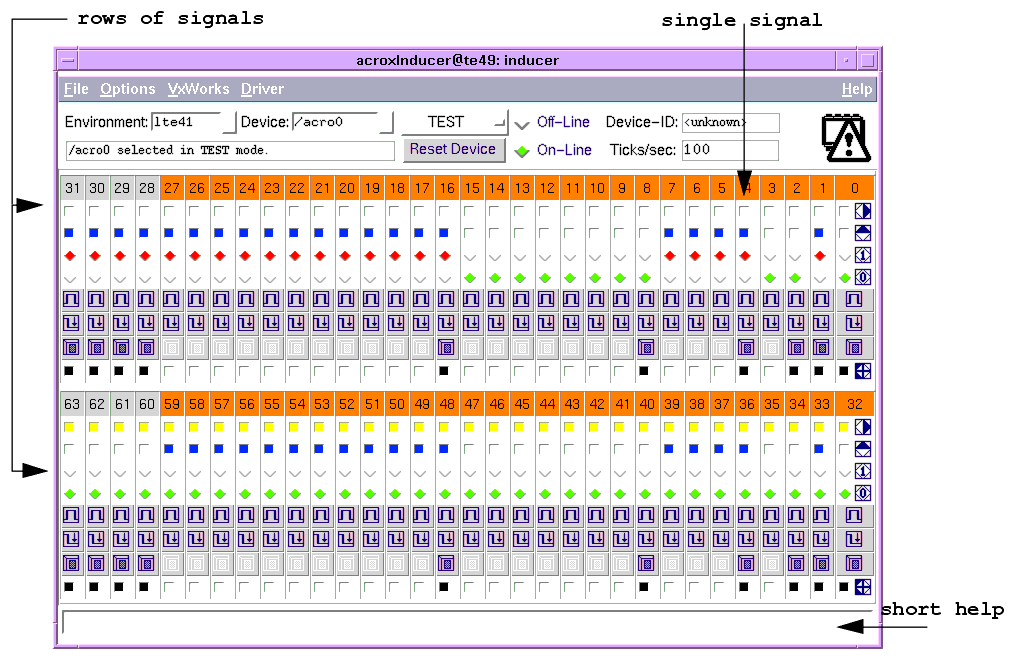
The panel in the figure below shows the physical appearance of the tool. It provides the functionality of the device and the corresponding driver via control elements representing individual digital signals. Your actions are immediately forwarded to the connected device, and changes of the device status are immediately displayed on the panel as well.

Besides the common panel part, the panel shows in one or two rows the digital signals. For each signal its number, state and current configuration is displayed. At the right side of each row of signals you will see a legend explaining the purpose of the corresponding control element. Furthermore if you point with the mouse over any interface element you will get in the panel's "Short Help Area" a brief description of its behavior.
4.3 Single Signals
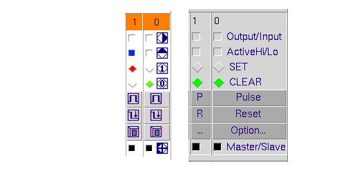
The figure below shows two signals belonging to the same row of signals, using textual labels or corresponding symbols.
 Signal number in the range from 0 to 63. It can change its color to orange when the signal is LCC configured, or when a non-empty signal name has been loaded from a file.
Input/Output configuration: This shows you if the signal is configured as Output or Input. If the button is yellow then the signal is configured as Output. You can click on the button to change the signal direction (the colour will change accordingly).
Active state configuration: This button shows you if the signal is configured to be active High or Low. If the button is blue then the signal is active High. You can click on the button to toggle the signal activity.
Set Button: If this button is red then the signal is SET (1/active). You can click on the button to SET the signal. Note that only one of the Clear/Set buttons can be active at any time.
Clear Button: If this button is green the signal is CLEARed (0/inactive). You can click on the button to CLEAR the signal. Note that only one of the Clear/Set buttons can be active at any time
Pulse Button: Pressing this button you can change the signal state (pulse) for a period of time. You specify the pulse-width using the signal's "Options Panel" (see section 4.4).
Options Panel Button: This button exposes an options panel that allows you to work with signal groups, names and to set the pulse width in ticks (see section 4.4).
Master/Slave Indicator: This Button can be manually modified or is automatically set/reset when you load a previously saved panel data file or the LCC Configuration. If there is a group configured the first signal of the group is the Master (the button is black) and the others are the slaves.
The figure shows also that only the rightmost signal in every row (signal number 0 in this case) has legends explaining the purpose of the corresponding widget. This is needed to save space. The behavior of the every widget will be the same of its rightmost counterpart. In addition, if you position the mouse over any widget, it will display a "Short Help Text" describing its behavior.
As a general rule, whenever you have a two state button (those with legends like <1st state>/<2nd state>) it is in the first state when the button is selected (you will note it because it will have a color different of grey), otherwise it is in the second state.
4.3.1 Signal Configuration
Each signal displays its current direction and active settings. The first two buttons of each signal shows you that information and allows you to set it as you want.
The button labelled "Output/Input" controls the signal direction and the button labelled "Active-Hi/Lo" the active state of the signal. Clicking the button toggles the corresponding setting. If the Signal is configured as Output you will see the related button yellow. The signal activity button is blue if the signal is configured to be active High.
For active-High signals a binary `1' refers to physical HIGH level, while for active-Low signals a binary `1' means physical LOW level.
4.3.2 Signal State
There are two buttons related to signal state. They are labelled SET and CLEAR meaning that the signal is active or not. Note that only one of them can be active at any moment. You can set or clear the signal by pressing the corresponding button. If the signal is SET the Set button is red, otherwise the CLEAR button is green.
4.3.3 Master and Slave Signals
If there are any group of signals configured when you load the LCC configuration, the first signal of the group will be set as Master (button's color is black) and the others will be set to slaves. You have to do it manually when you set a group using the Options panel. This Master and slave setting is intended as a visual aid and is not directly related to any driver's functionality. Note that for Slave signals the Option Panel button is disabled, so that it cannot be invoked.
4.4 Signal Options Panel
The above figure shows the options panel that is exposed for each signal when you press its "Options Panel" button.
In the upper part of the panel you have an entry to assign a name to the signal, it is also where the LCC name of the signal is displayed.
To pulse the signal there is a scale, below the signal name, that allows you to set the pulse width in ticks, then you press the signal's Pulse button in the main panel or the Pulse button at the left side of the scale. You can reset the pulse at any time pressing any of the signal's Reset buttons.
The lower part of the panel is devoted to group handling. It allows you to set a group of signals (starting from the current signal) using the scale at the right side to set the group's width. The column of buttons labelled Read, Write and Clear allows you to set and update the signal value, that is displayed in the entry at the left side of those buttons. Below the entry with the group value you have two radio buttons that controls the display format of that value. Below those buttons you have another row of four buttons, with those you can configure the whole group to be Input/Output Active Hi/Lo.
4.4.1 Signal Name
There is an entry at the top of the options panel that displays the name of the signal. The signal's name is coming from the LCC Configuration, a Saved Panel or you can name the signal typing something in the entry.
4.4.2 Signal Pulsing
You can output a single pulse to a signal (so that it temporarily changes its state) by pressing the signal's `Pulse'/'P' button. The signal will change its state for the period of time specified. You set the pulse width using the scale below the name entry at the right side of the options panel, the pulse width is expressed in ticks. You can see in the display `Ticks/sec' in the upper part of the panel how many ticks correspond to one second.
A setting of `0' (zero) ticks results in a very short pulse-width of about 10 microseconds. However, for widths shorter than 20 ticks you will hardly see a visible reaction in the signal's indicators, because the panel cannot display such rapid changes.
You can reset the signal pulse at any time pressing the Reset button.
4.4.3 Signal Group Handling
The options panel allows you to work with group of signals. To do that you must specify the group width using the "Group Width" scale. Using the columns of buttons located at the left of the group width scale you can Write or Clear the group value to 0 or Read it, using the corresponding button.
To set the group value you have to use the entry located at the left of the buttons and then press the Write button.
The group value is not automatically updated when it changes, you must press the Read button to get its current value.
You can enter the group value at any time in decimal (beginning with `1' to `9') or hexadecimal (beginning with `0x') format. You can specify the display format of the value as Hexadecimal or Decimal using the buttons below the "Group Value" entry.
Finally you can configure the whole group in an uniform way using the row of buttons located at the bottom of the panel, it allows you to configure the group in any combination of Input/Output and Active Hi/Lo.
Note that group handling does not work in Off-Line mode.
4.5 Load and Save Panel Data
The panel supports to save and re-load its contents into/from a file, as described in section 2.6.1. The following panel-specific values will be saved:
The order of the above keywords in the produced file must not be changed.
4.6 LCC Signal Support
The panel supports to load the LCC configuration for the device from the LCU, as described in section 2.6.2.
When you select the "Options>Load LCC Config" menu then each signal currently present in the panel is configured using the data retrieved from LCC, if exists. It includes signal name, signal configuration, state and group width. Note that the procedure to get the LCC configuration can take some time. The completion will be indicated by a dialog-box; do not enter new inputs before that time.
4.7 Known Problems
|
Quadralay Corporation http://www.webworks.com Voice: (512) 719-3399 Fax: (512) 719-3606 sales@webworks.com |