![[ ESO ]](/images/eso-logo.gif)
known problems
| HOME | INDEX | SEARCH | HELP | NEWS |
![[ ESO ]](/images/eso-logo.gif) |
|||||
|---|---|---|---|---|---|
| FORS1 Quality Control:
known problems |
|||||
|
|
Lamp Reflections
FORS1 Screen Flats (IMG mode) presently show three spots of artificial light which are due to lamp reflections on the LADC surface. If you plan to use the Screen Flats for reduction, these areas will need special treatment. FORS1 Screen Flats (LSS mode) show structure due to lamp reflections on the ADC surface. These are well off the central part which is usually exposed to the SCIENCE object. For extended objects, the Screen Flats have to be used with care.
Shadowing of CCD columns All FORS1 data taken later than 1999 November 01 have the last ~20 columns
(excluding the postscan region) shadowed out. This region is useless.
CCD pre-scan regions
A steep gradient is finally visible in column 15 and 16. A mesh of all 1024 rows of port A in a FORS1 bias taken in April 2001 is shown here (click here for the ps file). Despite this behavior, the pre-scan has been proven to be reliable in tracing the short time scale bias fluctuations (of the order of a 1-2 ADUs during a night). The user should exclude columns 15-16 from the statistics when scaling the bias frames during the reduction process and use the same region for statistics in both calibrations and science frames, to take into account in a proper way the pre-scan gradient. This effect is related to the pre-amplifiers of the FIERA CCD controllers. It has not proved possible to eliminate it completely without changing the electronic components. The pre-scan level has been shown to be also weakly dependent on the median exposure level of the image. This effect causes an increase of the order of a few ADUs for a median exposure level of 40 kADU, and hence has no practical consequences on science exposures. This effect is actuallyvisible on high exposure level flats only . IMPORTANT NOTE: due
to a feature of the FIERA controller, only full frames have pre-scan regions,
windowed frames don't.
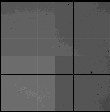
CCD contamination Contamination is a well known problem of the
FORS1 CCD. Since this is a time-dependent effect, its growth
is routinely checked as part of the instrument trend analysis. Dark Current Dark current trend plots have shown that
the Dark current is stable at the level of about 8 electrons/hr/pixel.
FORS1 Darks frames show a slight gradient along the columns, being the
maximum and the minimum 6 and 10 electrons/hour/pixels respectively.
Image Fringing
Of course to produce this interference pattern one needs to have a monochromatic source, otherwise the fringe pattern is cancelled. For this reason the fringes are seen in night images only and do not appear in screen or twilight flats, where the continuum contribution is very strong. Instead, during the night, the sky lines are the dominating background source and, specially in the red, they can produce significant fringing patterns. For a more detailed description of this problem and its possible solutions, please refer to: Electronic Imaging in Astronomy, I. S. McLean, Wiley, 1997. In the case of imaging, fringes become relevant in the z_GUNN filter only.
A standard procedure to eliminate the fringing is to obtain several frames of the same field using the dithering technique, i.e. offsetting the telescope between one frame and the other. This works particularly well if no extended objects are present, as it is the case in the example shown above. If extended objects are present, then the user should plan the observation of an adjacent field, just to be able to produce the proper nightflat.
Dust Contamination

|
|||||||||||||||||||||||||||||||||||||||||||||
|
|
||||||||||||||||||||||||||||||||||||||||||||||
 |
|
|||||||||||||||||||||||||||||||||||||||||||||