Quality Control and
Data Processing
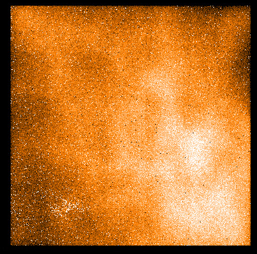
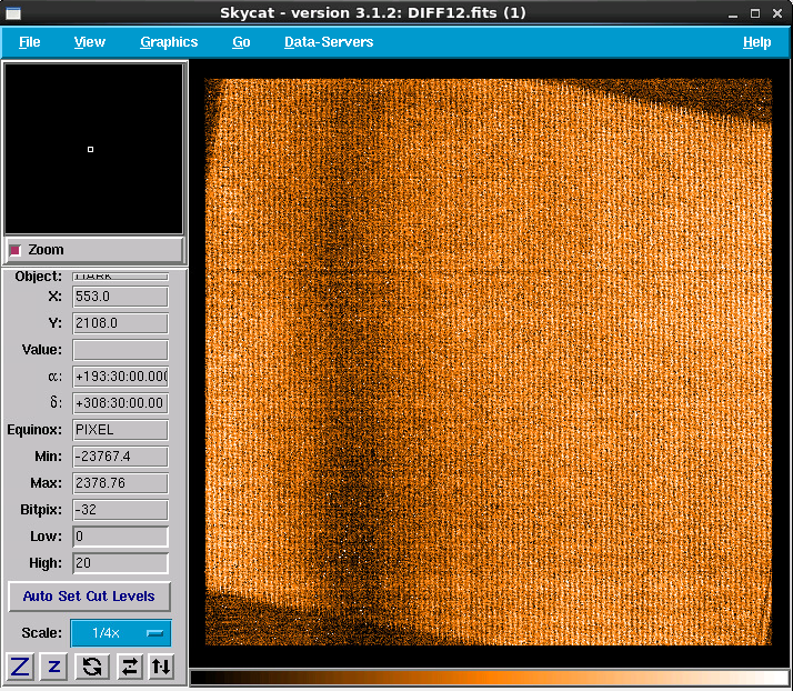
SPHERE: IFS Dark
The IFS-arm NIR detector is operated in cube mode (NDIT=NAXIS3) and nondestructive readmode (DET.READ.CURNAME=Nondest). All NDIT subintegrations are resolved as NDIT=NAXIS3 planes in a cube with 2048x2048 pixel (times NDIT planes). Detector characteristics are monitored via two raw types: DARK and BACKGROUND calibrations. Only BACKGROUND frames are used to calibrate science data. DARKs are acquired for monitoring the instrumental health.
 IFS Dark level
IFS dark frames are taken in regular intervals for the following setups
which are trended together in the upper part of one HC plot. The lower left plot shows the linear relation between the dark level and the exposure time. The marked relation of dark level(DIT) = -6 +10.2 * DIT refers to the relation for T_bench=16 deg. The lower central plot shows the values of the IFS bench temperature sensor with time. The lower right plot monitors the relation between the dark level and the bench temperature for the three mentioned setups. In addition dark frames are also acquired with the DIT and NDIT of the science observations. The darks come as a single frame with one cube (NAXIS=3). Scoring&thresholds IFS Dark level The dark levels are scored for three setups, relaxed thresholds have been chosen.
The pipeline uses the median dark level of the raw frame cube in ADU.
IFS Readout noise
The IFS detector readout noise is monitored for the same three setups as for the dark level in the upper part of the plot. The lower left box shows the relation between statistical noise and exposure time DIT. The marked square root law of RON(DIT) = 2.47 + sqrt(-6 + 10.2 * DIT / 3.6) means that the static detector noise is 2.47 ADU and the measured RON is contaminated by photon noise sqrt(counts / gain) induced by the dark current ( = -6 + 10.2 * DIT). The lower central plots shows IFS T_bench temperature values
Scoring&thresholds IFS Readout noise The three reference setups (DIT=2, 8, and 30) are scored according to the dashed lines in boxes 1,2, and 3. All other setups are scored according to the non-linear arithmetic relation indicated by the dashed curves in box 4.
No remarks. From the raw frame fits cube, five planes are extracted (plane 6 to 10), and for each pixel the stdev (out of five independent reads) is calculated. The median over all pixels stdev is taken.
IFS Hot pixel number
The number of hot pixel is monitored for the same three setups are for the dark level and the ron. Scoring&thresholds IFS Hot pixel number The scoring thresholds are based on statistical grounds. No remarks. Algorithm IFS Hot pixel number A smoothed version of the master dark is subtracted from the master dark to eliminate background gradients. Pixel which deviate more than 5 sigma from the difference product are flagged as hot pixel.
|
|||||||||||||||||||||||||||||||||||||||||||||||||||||||||||||||||||||||||||||||||||||||||||||||||||||||||||||||||||||||||||||||||||||||||||||||||||||||||||||||||||||||||||||||||||||||||||||||||||||||||||||||||||||||||||||||||||||||||||||||||||||||||||||||||||||||||||||||||||||||||||||||||||||||||||||||||||||||||||||||||||||||||||||||||||||||||||||||||||
| |
|||||||||||||||||||||||||||||||||||||||||||||||||||||||||||||||||||||||||||||||||||||||||||||||||||||||||||||||||||||||||||||||||||||||||||||||||||||||||||||||||||||||||||||||||||||||||||||||||||||||||||||||||||||||||||||||||||||||||||||||||||||||||||||||||||||||||||||||||||||||||||||||||||||||||||||||||||||||||||||||||||||||||||||||||||||||||||||||||||
 |
|
||||||||||||||||||||||||||||||||||||||||||||||||||||||||||||||||||||||||||||||||||||||||||||||||||||||||||||||||||||||||||||||||||||||||||||||||||||||||||||||||||||||||||||||||||||||||||||||||||||||||||||||||||||||||||||||||||||||||||||||||||||||||||||||||||||||||||||||||||||||||||||||||||||||||||||||||||||||||||||||||||||||||||||||||||||||||||||||||||