Quality Control and
Data Processing
SPHERE: IRDIS pinhole mask
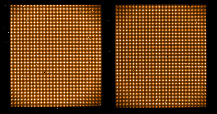
The IRDIS arm optical distortion calibration (CI, DBI and DPI) is an image of a pinhole mask. The pinholes have diameter of 30 micrometer and a distance of 100 micrometer from each other in the focal plane. This transforms into a distance of 13.963 pixel on the detector and a nominal diameter of 4.2 pixel. (Given the image scale of 12.25 mas/pixel, this results in 51.45 mas and 171 mas). The pipeline retrieves the optical distortion correction. The correction functions are given in several extensions of the pipeline product. IRDIS pinhole mask calibrations are acquired during daytime. The template generates one raw frame. IRDIS pinhole mask images are acquired once a week with the following setups: In IRDIS-CI mode in four broad band filters Y, J, H, and Ks without apodizer and without coronographic pupil stop. In IRDIS-DBI mode in two double beam filters D_H23 (+ B_H) and D_K12 (+ B_Ks) once without apodizer and without ALC2 pupil stop and once with apdizer and with ALC2 pupil stop.
 IRDIS optical axis position
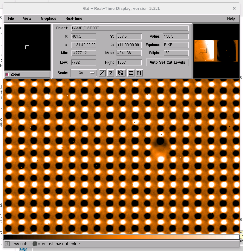
The pinhole mask which is located before the folding and the tip-tild mirrors is projected with minor shifts onto the detectors, depending on the current status of the deformable mirror. The optical axis position is derived as the center of the projected pinhole mask. Some pinhole calibration images are acquired with the apodizer mask which generates a black feature in the center of each channel and obscures the central pinhole. Unsuitable shapes of the deformable mirror produce fuzzy pinhole PSFs with consequenctly useless information. Since the grid of the mask is larger than the FOV, pinhole mask shifts of more than 7 pixel cannot be reliably resolved, as the distance between each pinhole is only 14 pixel.
Scoring&thresholds IRDIS optical axis position The optical axis position is scored for CI (four broad band filters, no apodizer) and for DBI (two broad band filters, no apodizer). The thresholds have been set to the median plus minus 14 pixel, which is the distance between two pinholes.
From 2018-01-01 on the optical distortion frames are processed with pipeline version 0.37. Algorithm IRDIS optical axis position See the pipeline user manual
IRDIS optical distortion
The pattern of the rectangular pinhole mask is projected with an optical distortion onto the detector. The data reduction pipeline recipe fits the optical distortion via a polynomial. The temperature (INS4.TEMP449.VAL, the common path cabinet ambient temperature) dependence of the coefficients X_1_0 and Y_0_1 (see Algorithm), which contain the image scale are monitored for the left and right channel and all filters separately. In DBI mode, the anamorphism is trended as well, the ratio between the image scale in Y- and X-direction. Scoring&thresholds IRDIS optical distortion The relation image scale versus instrument temperature is not scored. IRDIS optical distortion frames of 2015 and from 2018 on are re-processed with pipeline version 0.37. Algorithm IRDIS optical distortion For each pixel position x, y the optical distortion correction is expressed by two polynomials, one for the offset in X:
|
|||||||||||||||||||||||||||||||||||||||||||||||||||||||||||||||||||||||||||||||||||||||||||||||||||||||||||||||||||||||||||||||||||||||||||||||||||||||||||||||||||||||||||||||||||||||||||||||||||||||||||||||||||||||||||||||||||||||||||||||||||||||||||||||||||||||||||||||||||||||||||||||||||||||||||||||||||||||||||||||||||||||||||||||||||||||||||||||||||||||||||||||||||||||||||||||||||||||


| IRDIS optical axis position | IRDIS optical distortion | IRDIS optical distortion correction |
| FITS key | QC1 database: table, name | definition | class* | HC_plot** | more docu | |||||||||||||||||||||||||||||||||||||||||||||||||||||||||||||||||||||||||||||||||||||||||||||
| [derived from QC procedure] | sphere_irdis_distmap..dx12 | HC | | [docuSys coming] | ||||||||||||||||||||||||||||||||||||||||||||||||||||||||||||||||||||||||||||||||||||||||||||||
| [derived from QC procedure] | sphere_irdis_distmap..dey12 | HC | | [docuSys coming] | ||||||||||||||||||||||||||||||||||||||||||||||||||||||||||||||||||||||||||||||||||||||||||||||
| *Class: KPI - instrument performance; HC - instrument health; CAL - calibration quality; ENG - engineering parameter **There might be more than one. | ||||||||||||||||||||||||||||||||||||||||||||||||||||||||||||||||||||||||||||||||||||||||||||||||||
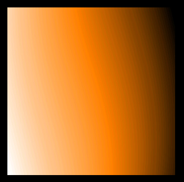
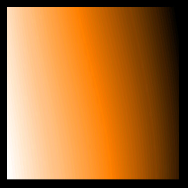
The IRDIS image and its scale is stretched by the optical distortion and must be shrinked by the optical distortion polynomial. The offset (applied in later steps of the data reduction cascade) is monitored for four points in the FOV which are 250 pixel away from the center (512,512) in x and in y: [512+250 : 512+250], [512+250 : 512-250], [512-250 : 512+250], [512-250: 512-250]. It is also applied to a second set of four points in the FOV, which are 500 pixel of the center, hence very close to the corners of the FOV.
Scoring&thresholds IRDIS optical distortion correction
The offsets are not scored
From 2018-01-01 on the optical distortion frames are processed with pipeline version 0.37.
Algorithm IRDIS optical distortion correction
The polynnomial is applied to eight points in the FOV.

| Send comments to <qc_sphere@eso.org> | powered by QC [webCMS v1.0.1] |