
GALACSI
Contents
- Overview
- Optical layout WFM
- Optical layout NFM
- Calibration and diagnostic systems
- Mechanical Implementation
- Expected Performance
- Status
Overview
GALACSI is part of the Adaptive Optics Facility (AOF), and associated with the DSM and the 4LGSF it defines an AO system developed to increase the performance of the MUSE instrument, a panoramic integral-field spectrograph working at visible wavelength built by a consortium led by .CRAL.The system GALACSI combined with the MUSE instrument is dubbed MUSE facility.
GALACSI will use 4 Na-LGS (sodium Laser Guide-Stars) launched from the centre piece of a Unit Telescope of the VLT and the light re-emitted by the 80-100 km altitude Sodium layer is collected by 4 WFS (Shack Hartmann Wave Front Sensors) each with 40x40 subapertures. The slopes measured by the WFS are combined by the Real Time Computer SPARTA to estimate of the Wave Front Error introduced by the earth's atmosphere and to calculate the correction applied to the DSM. The AO-loop is closed at a 1000 Hz frequency.
GALACSI and GRAAL benefit from several common developments for the AOF and other applications. Specifically these are the DSM and the ASSIST test bench, 4-LGSF, NGC WFS camera and the SPARTA Real Time Computer platform.
MUSE facility will offer 2 instrument modes. The type of AO correction the nature of the tip tilt star and the location of the LGS differ between both modes
- In the Wide Field Mode MUSE will cover 1' by 1' field of view with a sampling of 0.2" per spatial pixel. GALACSI is requested to double the ensquared energy within one spatial pixel over the FoV of the MUSE spectrograph. The 4 LGSs are 64" off axis to probe atmospheric turbulence and the averaged WFS signals will be used to correct for the turbulent ground layer. One visible Natural Guide Star is used to correct for the remaining atmospheric tip-tilt.
- In the Narrow Field Mode MUSE will cover 7.5" by 7.5" field of view with a sampling of 0.025" per spatial pixel. GALACSI is requested to provide low Strehl Ratio at 650nm and to deliver near diffraction limited images. The 4 LGSs are 10" off axis to probe atmospheric turbulence. A tomographic algorithm is used to calculate the wave front error in the center of the field of view and the correction signal applied to the DSM. In addition, the infra red light of one Natural Guide Star is used to measure the remaining atmospheric tip-tilt, defocus and astigmatisms.
| - | Wide Field Mode | Narrow Field Mode |
| MUSE field of view | 1' by 1' | 7.5" by 7.5" |
| Size of a spatial pixel | 0.2" by 0.2" | 0.025" by 0.025" |
| AO performance | double the ensquared energy in one spatial pixel at 750nm | 5% Strehl at 650nm (goal 10%) |
| Type of AO correction | Ground Layer AO | Laser Tomographic AO |
| Tip Tilt star brightness | <17.5 R-mag | <15 J-H mag |
| Tip Tilt star location | 52" to 105" off axis --> >70% Sky coverage | on axis, within 7.5" diameter |
| Laser Guide Star separation | 4 LGS 64" off axis | 4 LGS 10" off axis |
Optical layout WFM
In its Wide Field Mode the laser guide stars are located at 64" off-axis e.g. outside the scientific field of MUSE. The Visible Tip-Tilt Natural Guide star with a magnitude up to MR~17.5 will be located within a 3.5' technical FOV but outside the 1' square FOV of MUSE. This minimizes the impact to the scientific beam path by dichroic beam splitters or pickup mirrors for both, the LGSs and the Natural Guide Star.
The Separation of the technical light path from the Scientific beam path is done with an annular mirror located near the Nasmyth focal plane. It lets pass through the central 1.4' of the field towards MUSE and reflects the light towards the LGS and TipTilt Wavefront Sensor paths. By means of a Sodium (Na) Dichroic the Laser Guide Star light is reflected towards the focus compensator, and a telecentricity lens. A reflecting pyramid sends then the 4 LGS beams towards their WFS paths. Each of them consists of a Pupil re-imaging lens, a jitter actuator, and an additional pupil relay to create the pupil on the WFS lenslet array.
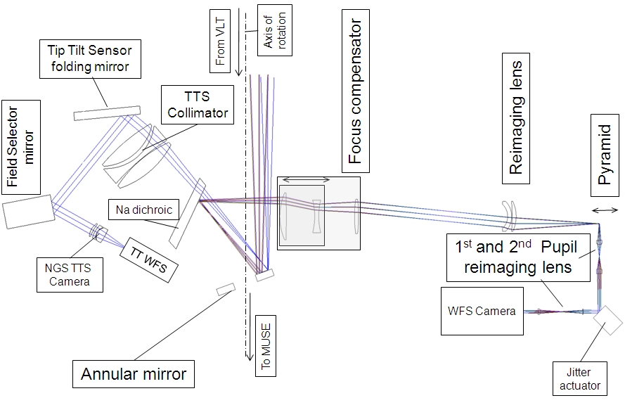 |
| Optical Layout of the Vis. TTS and LGS path of GALACSI. Only one of the 4 WFS paths is shown. |
Most of the visible light passes through the Sodium Dichroic towards the Tip-Tilt Sensor. A collimator forms pupil in which a motorized tip tilt mirror (Field Selector) allows to direct only part of the field to the Tip-Tilt Sensor.
Optical layout NFM
To switch to Narrow Field Mode the off axis distance of the LGS will be reduced to 10" off-axis and a dichroic mirror is inserted in the central aperture of the annular mirror. It reflects the 589nm light of the LGSs towards the WFS beam path and transmits the light with other wavelengths.
The wave front errors invisible to the LGS-AO system are measured with an InfraRed Low Order Sensor. It is a Shack Hartman sensor with 2 by 2 sub apertures working at a wavelength range of 980nm to 1800nm. To allow a very good image stability, IRLOS is embedded inside the MUSE fore optics
 |
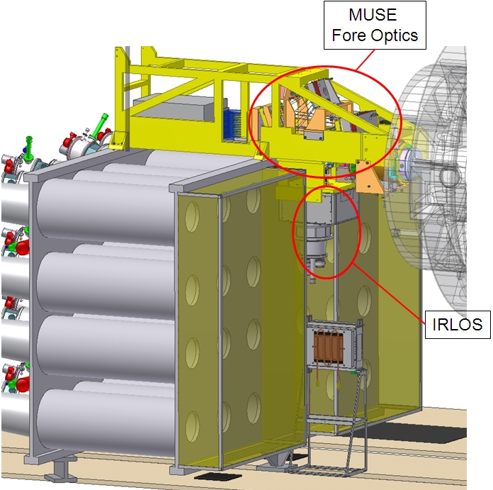 |
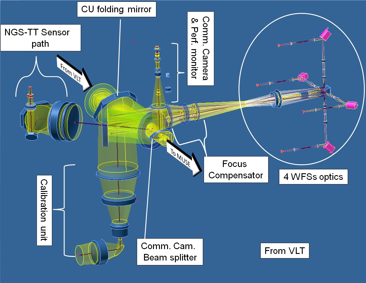
| All optical components of the GALACSI main assembly | IRLOS embedded in the MUSE assembly |
Calibration and diagnostic systems
For the Calibration of its subsystems GALACSI hosts a Calibration unit. It consists of an objective imaging a source plate to the Nasmyth focal plane. It provides point sources to calibrate the WFSs, the field selector position and tracking as well as a point source with sub diffraction limited diameter for performance characterization of the NFM. The whole assembly can be moved in focus to correctly simulate the LGS properties.
For performance verification and testing a Commissioning Camera is implemented. A pellicle beam splitter moved into the beam path directs part of the light to a 1024 pixel by 1024 pixel technical CCD camera. The plate scale of the camera can be changed to either cover the MUSE field or to sample the diffraction limit of the VLT at visible wavelengths. A filter wheel in front of the camera allows selecting the wavelength range. The whole assembly can be focused to image normal stars as well as the LGSs.
Mechanical Implementation
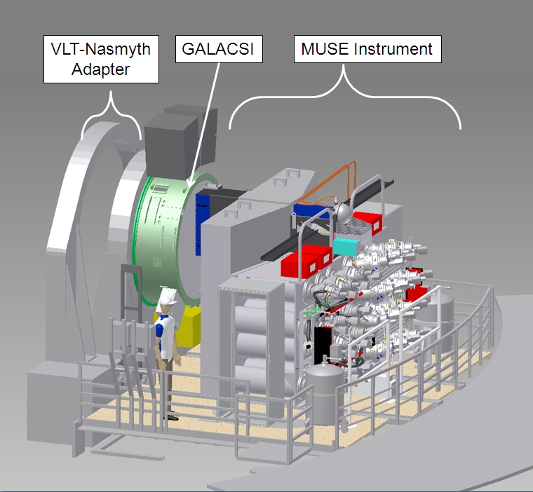
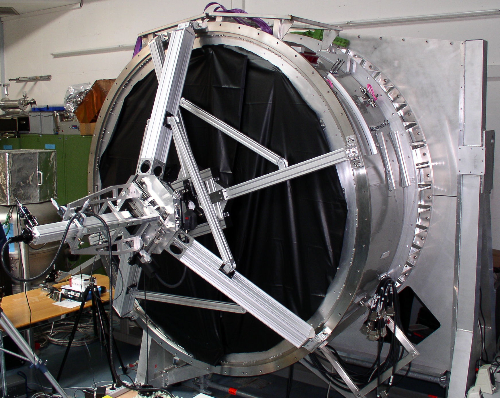
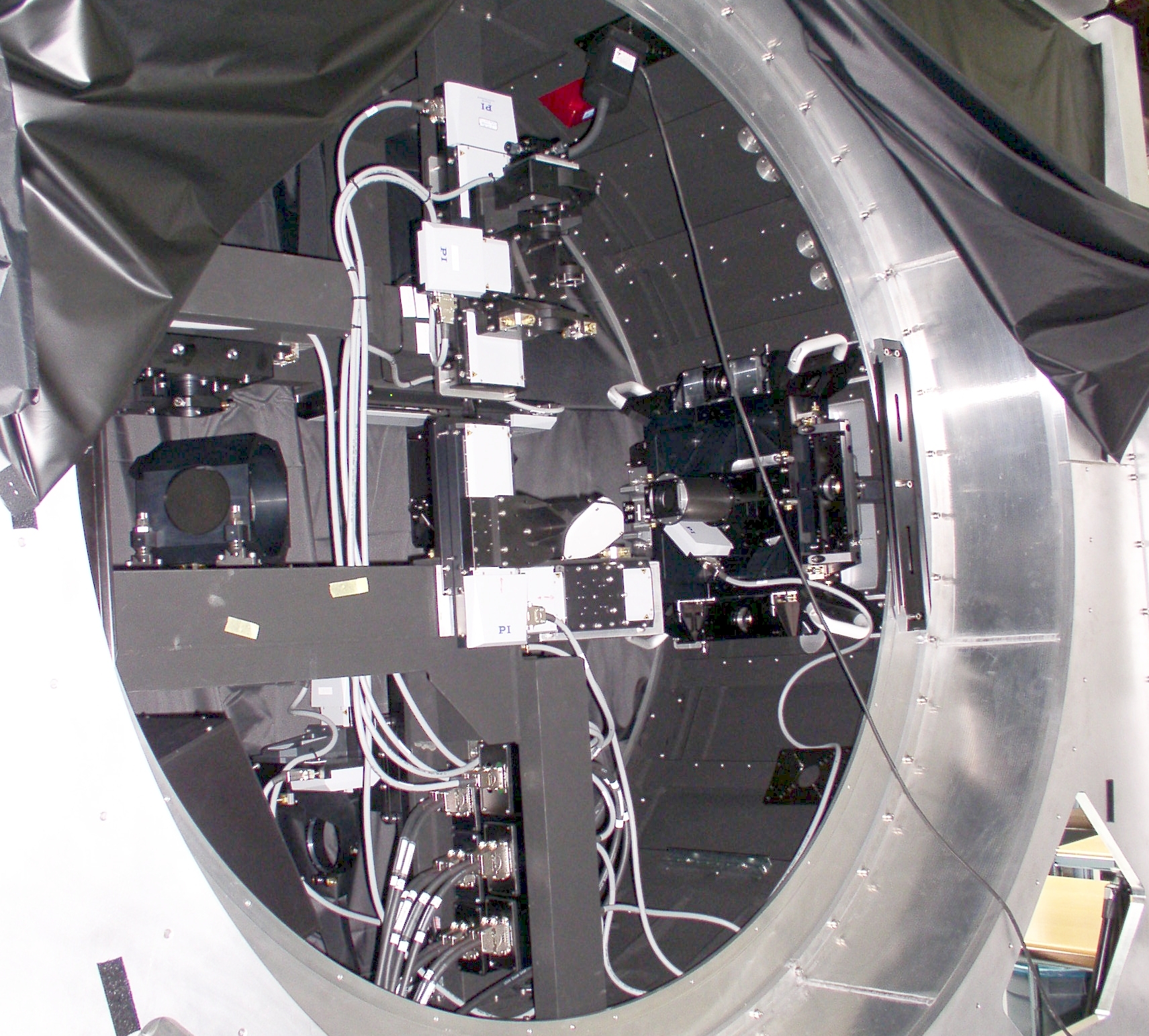
All opto-mechanical units of GALACSI except IRLOS are hosted in a cylindrical structure and are attached to the VLT Nasmyth rotator. 5 cabinets hosting electronics requiring a short cable length are attached to the GALACSI structure. Fibers for the network connection the power and cooling supply lines are guided to the main assembly be 2 cable chains.
 |
 |
| MUSE Facility on the VLT Nasmyth Platform. The GALACSI main assembly is the green cylinder attached to the VLT Nasmyth adapter. | GALACSI main assembly (covers removed) |
Expected Performance
In Wide field mode the GALACSI performance is measured in the gain of the squared energy within 0.2" by 0.2" with respect to the seeing limited case. This allows to detect fainter objects within the same exposure time and to distinguish finer details compared to a seeing limited observation.
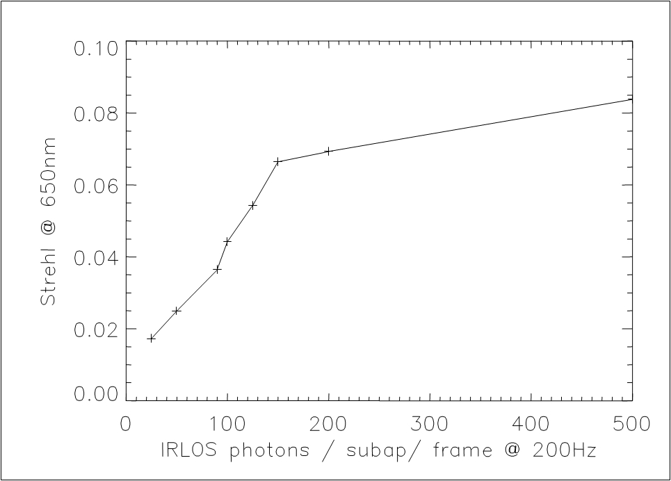
In Narrow Field Mode the performance is measured in Strehl ratio. Even though the Strehl value seems rather low, this mode will provide a near diffraction limited resolution at visible wavelengths at the VLT!
The expected performance of GALACSI taking into account the instrumental error budget is given in the figures below.
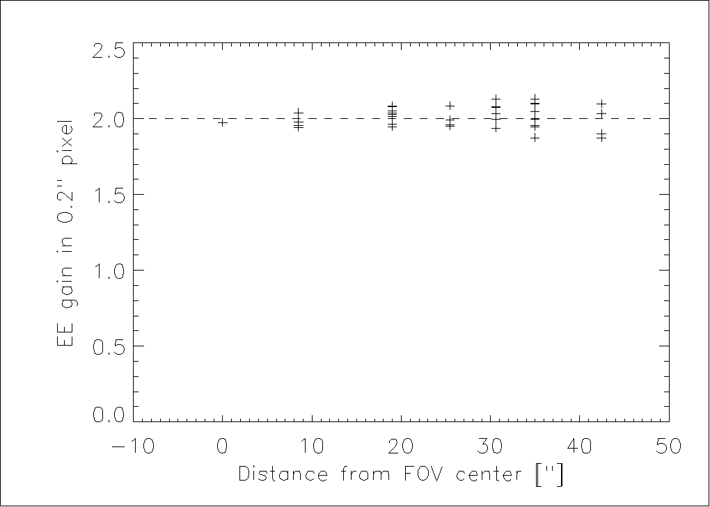 |
| GALACSI WFM ensquared Energy gain at 750nm for 1.1" seeing |
 |
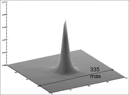 |
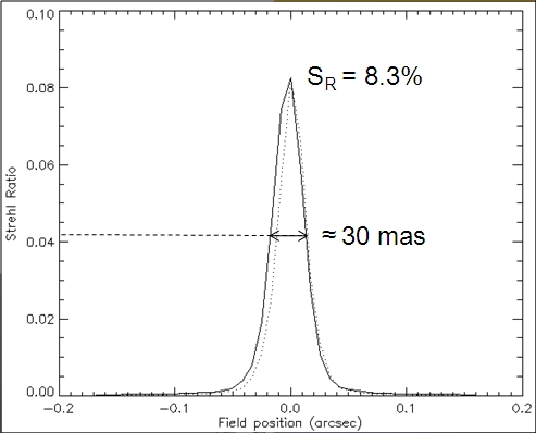 |
| GALACSI NFM Strehl ratio at 650nm and 0.65" seeing for different tip tilt stars with different brightness | Typical NFM PSF | Cross section of the typical PSF |
Status
GALACSI passed its Final Design review in June 2009. GALACSI system level integration and testing started in 2012. The System test phase with the DSM on the ASSIST test bench started in April 2015 with a planned PAE early 2016 and a subsequent commissioning.
Picture Gallery
In this section we present pictures accompanying the progress of the GALACSI development.
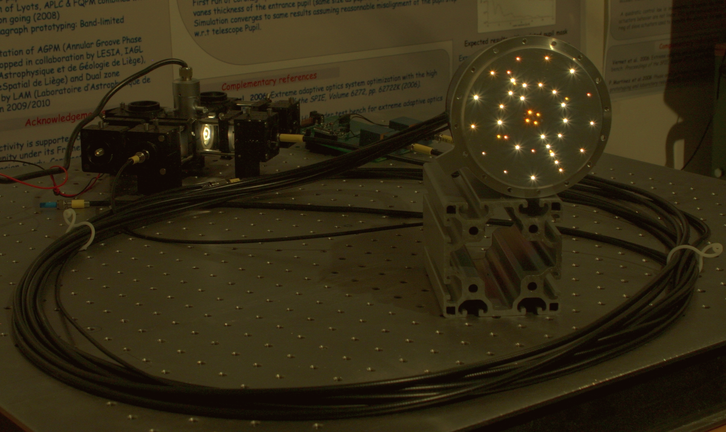 |
| Source module for the Calibration Unit. Fibers of different diameters, fed with light of different wavelengths to simulate NGSs and LGSs are precisely arranged in a metal plate. |
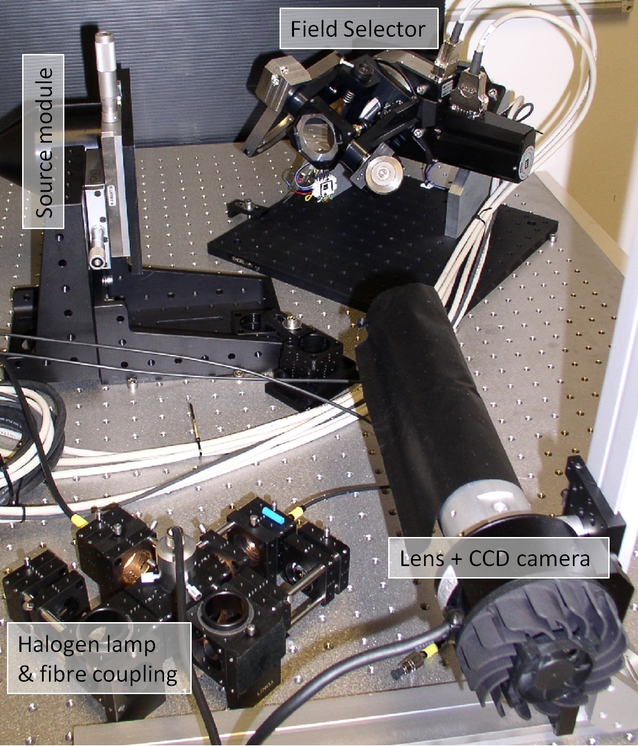 |
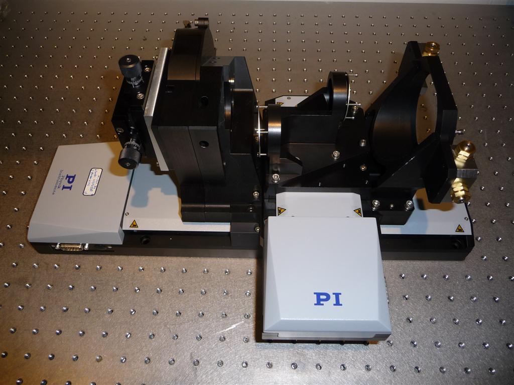
| Laboratory setup for the GALACSI field selector (WFM). Artificial stars created by the source module are imaged via the Field Selector mirror to a CCD camera. This setup allows a verification of the functions and accuracy. |
Mechanical parts start to arrive.
 |
| Some mechanical parts of GALACSI arranged together with the translations stages for the different subassemblies. |
update on March 7th 2011.
 |
 |
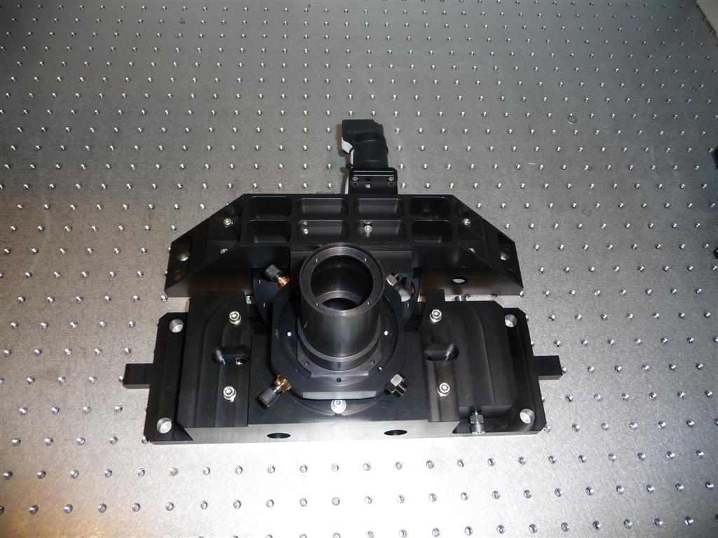 |
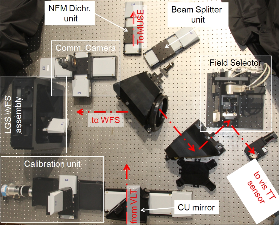
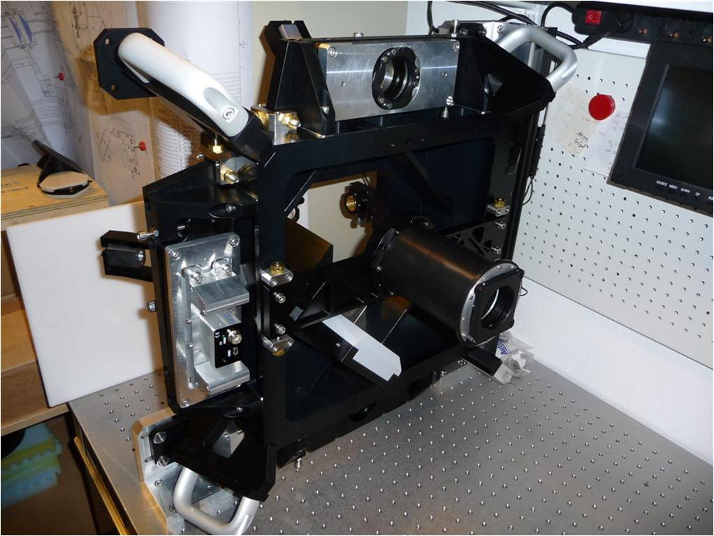
| Assembly of the Commissioning Camera | LGS path and WFS assembly | Munting interface for the Visible Tip Tilt Sensor and its filter wheel |
 |
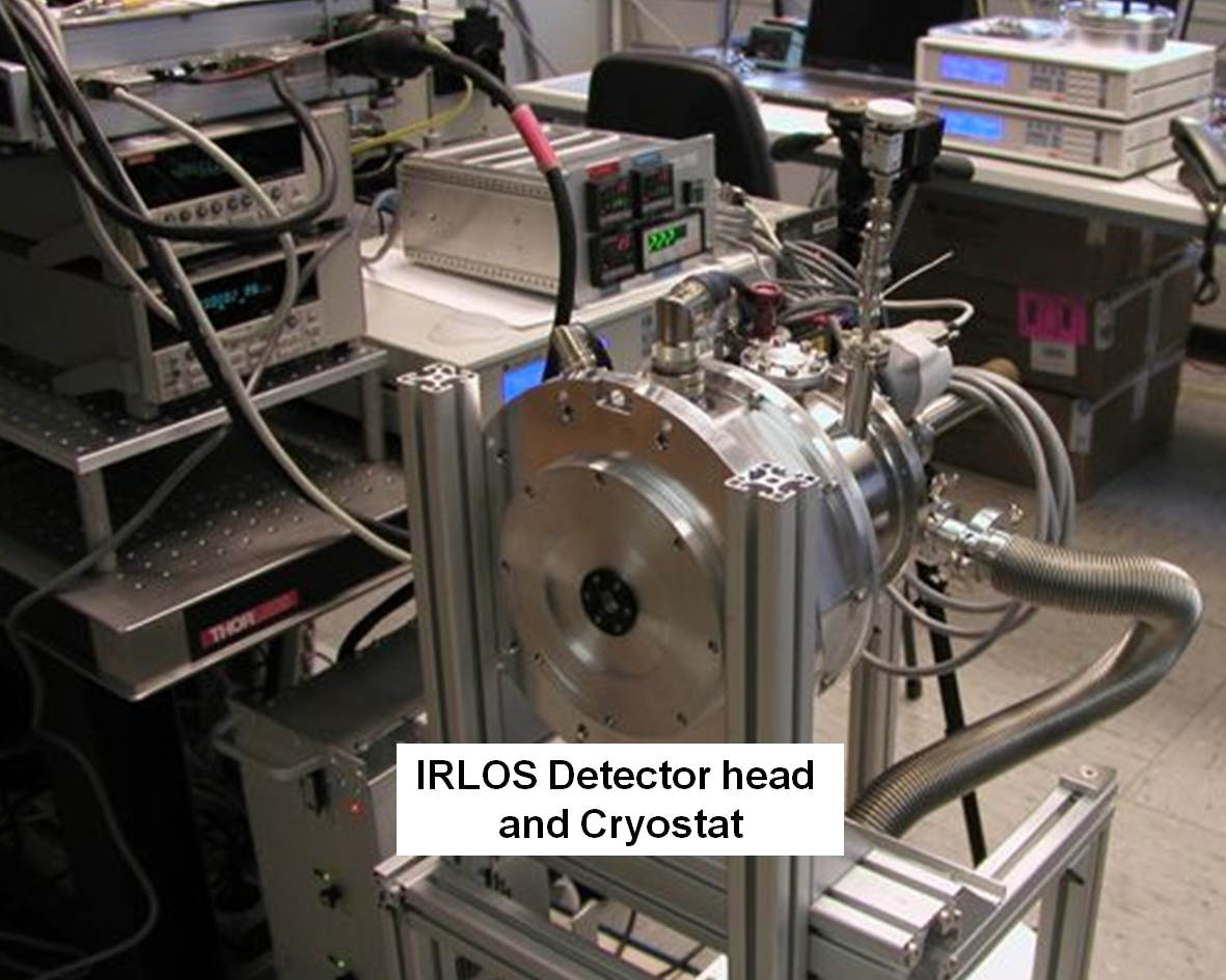 |
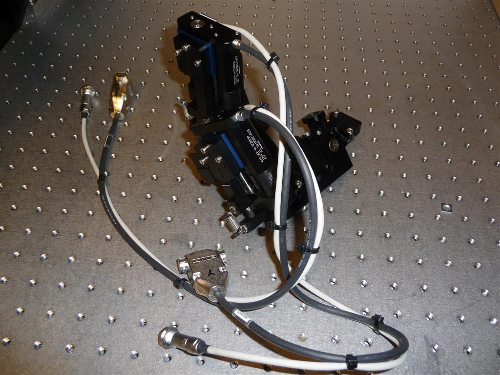
| IRLOS Field Selector | IRLOS Cryostat and Detector Controller (NGC) |
 |
 |
| GALACSI main assembly on its integration stand with the tool to define the VLT optical axis | GALACSI main assembly as seen from the back side (MUSE) with most subassemblies pre-integrated |
What's new?
Check for the next lunch Talk.
Quick Links
- Home
- Adaptive Optics group expertise and activities
- Adaptive Optics Systems
- Adaptive Optics Technologies
- AO lunch talks
- Other useful links
Special Event: 20 years of Adaptive Optics at ESO
Contact Us