
CUBES: Cassegrain U-Band Efficient Spectrograph

Content
The CUBES project will provide a high efficiency UV spectrograph at a VLT Cassegrain focus. The instrument will have a spectral range of 300-400nm and offer two resolutions of 20K and 7K.

| Builders |
The CUBES consortium:
|
| Principal Investigator | Stefano Covino (INAF-OABr) |
| Deputy-PI | Stefano Cristiani (INAF-OATs) |
| Co-PIs | Beatriz Barbuy (IAG-USP), Ruben Sanchez-Janssen (UKATC), Andreas Quirrenbach (LSW), Rodolfo Smiljanic (NCAC) |
| Project Manager INAF/ESO |
Roberto Cirami (INAF-OATs) / Omar Sqalli (ESO) |
| Project Scientist INAF/ESO |
Cyrielle Opitom (UoE) / Markus Schöller (ESO) |
Project Engineer INAF/ESO |
Matteo Genoni (INAF-OABr) / Paul Bristow (ESO) |
| Instrument Approval | January 2022 |
| Project Status | MAIT |
| Destination | Cassegrain focus of VLT UT1/2/3/4 |
Baseline Specifications
| Spectral Resolution | ~20000 (~7000 LR mode also provided) |
| Wavelength Range | 305 - 400nm |
| Slit length/width | HR: 10" x 1.5" (sliced into six 0.25" slitlets) LR: 10" x 6" (sliced into six 1" slitlets) |
| Efficiency | >40% |
| Focus | UT1/2/3/4 Cassegrain |
| Sensitivity |
S/N>20 for U=18 mag at 313 nm (0.007nm wavelength bin) |
| Acquisition and guiding | Vref~22, photometry error<10% |
Status and provisional timeline
- Science operations from – 2030
- Commissioning, expected – Q4 2029
- Transfer to Paranal and installation, expected – Q3 2029
- Preliminary Acceptance Europe (PAE) expected – Q1 2029
- Current Status: MAIT
- Final Design Review (FDR) Passed - Q4 2024
- LLI review completed
- Preliminary Design Review (PDR) passed – Q4 2023
- Project approved – January 2022
- Phase A review, passed – July 2021
Scientific Objectives
Extragalactic
Primordial Deuterium abundance
Missing baryonic mass in the high-z circumgalactic medium (CGM)
The cosmic UV background
Transient
Galactic
Heavy elements in metal-poor stars
CNO abundances
Beryllium
Solar System
Searching for water in the asteroid belt
Measuring the N2/CO ratio in comets
Instrument Description
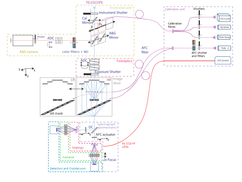
CUBES will consist of two main assemblies: the PRE-SLIT subsystem and the SPECTROGRAPH subsystem. The pre-slit unit consists of an image slicer, a slit viewer which is part of the A&G subsystem, a calibration unit and an ADC. The spectrograph consist of two arms, divided by means of dichroics, each with their optimized dispersing element, camera and detector systems. Throughout the optical path, optimising the UV photon efficiency is a high priority.
A&G Camera
A separate camera for the acquisition and guiding (A&G subsystem) is fed by a fold mirror close to the telescope focus. Four lenses reimage a 100arcsec diameter FoV onto a detector focal plane (GreatEyes ELSE-I 1K x 1K) at a plate scale of 130microns/arcsec. This will provide acquisition and guiding down to Vref~22 while offering an imaging mode that supports spectrophotometry by enabling relative photomtry accurate to 10%.
Slicer
- 6 slices each with a width of 0.25arcsec on sky
- Slit width on sky 1.5arcsec, no slit loss
- Physical slice width 0.5mm for ease of manufacture cf Keck Cosmic Web Imager
- Smaller beam size at grating (applies to any spectrometer design)
- Allows pupil to be reimaged on the grating

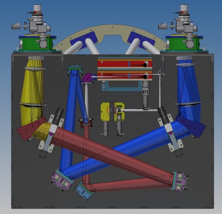
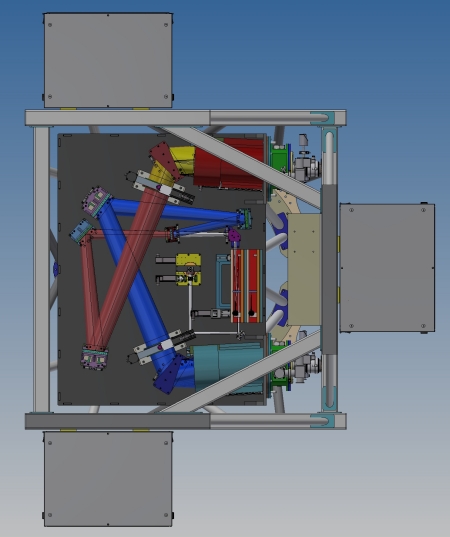
Spectrograph
- Split into 2 bands using dichroics with separate collimators, gratings and cameras
- 2 silica lens camera
- All surfaces spherical except for one
- Same set of components for each camera
- Chromatic focus offset by lens spacings and detector tilt
- Bands have 6nm overlap, to ensure complete wavelength coverage in one observation
Gratings
Custom gratings are being developed for CUBES and will be crucial for meeting the demanding photon efficiency requirements of CUBES.
- Footprint on grating 160mm (along grooves) x 195mm (dispersion direction
- Optimised for maximum transmission within each band
- No mosaicing necessary
Detectors
CUBES will employ two 9k x 9k CCD devices, each consisting of two halves . One half will be used to record the science spectrum, while the other half is read independently and used for real-time correction of instrumental flexure and thermal drift.
The detectors are standard silicon, backside illuminated devices and would be expected to use an AR coating currently under development at Teledyne-E2V. This coating “UV1-NEW” has optimal performance in target wavelength range of CUBES, 300nm to 400nm.
The CUBES project has adopted the ELT framework, and as such the detector control electronics will be the New Generation Controller II (NGC II).
Sunpower GT AVC has been chosen for the cryo-cooler, it provides adequate cooling power with relatively low vibrations whilst promising to reduce the maintenance load relative to the LN2 bath solution that has been traditionally used for similar instruments.
 Optical layout of the 2 channel spectrograph
Mechanical Design
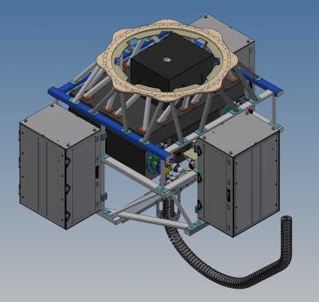
In order to achieve a resolving power of ~20000, CUBES requires a fairly large beam diameter (160 mm). Consequently, the instrument envelope is becoming rather large compared to other Cassegrain instruments (e.g., X-Shooter with 100 mm). Scaling classical instrument designs to the required size of CUBES would result in exceeding the mass limit of 2500 kg for UT Cassegrain instruments. Therefore, the mechanical design of CUBES adopts light-weight construction principles and makes use of modern composite materials.
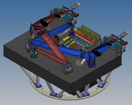
In the PDR design, CUBES main mechanical structure is divided into three main components:
- a telescope adapter, that provides a stiff connection between the Cassegrain telescope flange and the optical bench assembly of CUBES
- an optical bench assembly, that provides a stable platform for the spectrograph optics as well as for the fore optics
- a support frame assembly to provide support for auxiliary equipment of CUBES such as electronic racks, the calibration unit and vacuum equipment. This frame is detached from the optical bench assembly in order to mitigate flexure contribution from auxiliary equipment.

Calibration Unit
To maximise observing efficiency, as a rule all calibrations (except standard stars) will be done during daytime with the telescope at zenith. The goal is to provide a wavelength precision accuracy to a level of 1/10th of a resolution element, i.e. 1.5 km/sec.
The CUBES calibration sub-system contains the usual light sources for flat fielding (using a Laser-Driven Light Source) and wavelength calibration (using a ThAr lamp), The ThAr lamp provides an adequate spectral line density to drive the wavelength calibration.The light from the calibration unit is fed by a fiber to the Cassegrain focal plane where it is injected via the calibration mirror.
The calibration unit also supports instrument maintenance and alignment (e.g. after an earthquake) as well as Automatic Flexure Correction (AFC). A fiber (see schematic diagram above) illuminates a 7th AFC slit on one side of the 6 slicer slitlets. It generates a faint ThAr spectrum falling on the the AFC half of the CCD that is periodically read out.: An active optical component in each arm stabilizes the position of this spectrum (and thus also that of the science spectrum) at typically 10-minute intervals to better than ~1 um at the CCD.
Documents
A summary of the CUBES project appeared in issue 188 of the ESO Messenger
Further CUBES related papers: