SPHERE: IFS detector flats
| |
| HC PLOTS |
| counts in the bright YJ flat |
 |
| counts in the bright YJH flat |
|
| bad pixel number YJ master flat |
|
| bad pixel number YJH master flat |
|
|
QC1 database (advanced users):
browse |
plot
|
IFS imaging flats consist of two raw frames. One with a low exposure
time and one with a high exposure time. The pipeline recipe decomposes
the master imaging flat field in four components:
- a spatially high frequency fixed pattern noise product tagged DFF for differential flat field
- a spatially low frequency fixed pattern noise product (a smoothed flat) tagged "large scale"
- a preamplifier map product showing the extracted mean responses per amplified channel (vertical stripes)
a bad pixel map.
For the YJ prism the flats come in four setups: one broad band lamp and three narrow band laser lamps,
for the YJH prism the flats come in five setups: one broad band lamp and four narrow band laser lamps.
The next steps of the calibration cascade require the DFF products of the brand band lamp and the laser lamps and the pre-amplifier map product from the broad band lamp.
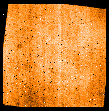 |
IFS high exposure time broad band lamp raw frame for the YJH prism.
|
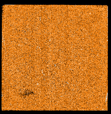 |
IFS DFF imaging flat product showing the spatially high frequency fixed pattern noise.
|
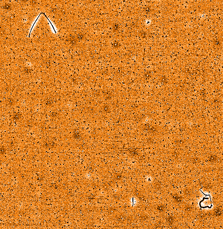 |
IFS DFF imaging flat product showing the spatially high frequency fixed pattern noise. zoomed view.
|
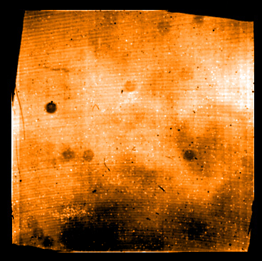 |
IFS imaging flat large scale feature (smoothed) product.
|
 |
IFS imaging pre-amplifier map product.
|
 IFS Detector flat counts
QC1_parameters
| FITS key |
QC1 database: table, name |
definition |
class* |
HC_plot** |
more docu |
| [QC procedure] | sphere_ifs_dflat..qc_lam_flux_avg_1 | ADU in raw frame 1 | HC | | [docuSys coming] |
*Class: KPI - instrument performance; HC - instrument health; CAL - calibration quality; ENG - engineering parameter
**There might be more than one. |
Trending
The instrumental background depends on the dichroic in the common path interface (CPI).
INS4.OPTI3.NAME=DIC_K means the YJH-bands are switched to IFS (and IRDIS receives the K-band alone).
INS4.OPI13.NAME=DIC_H means the YJ-bands are switched to IFS and H and K is switched to IRDIS.
Scoring&thresholds IFS Detector flat counts
The background rates are scored for both dicroic and three values of DIT.
History
- 2014-10-01: The template generates two raw frames, each one is a
fits cube ( NAXIS = 3 ) with five layers ( NAXIS3 = 5 ) corresponding
to NDIT=5 and with QC parameters:
QC.LAMP.FLUX.AVG.0 to QC.LAMP.FLUX.AVG.4 (from the first raw frame cube) and QC parameters:
QC.LAMP.FLUX.AVG.5 to QC.LAMP.FLUX.AVG.9 (from the second raw frame cube).
We plot qc_lam_flux_avg_1 (= QC.LAMP.FLUX.AVG.7 = middle layer of second cube).
LAMP_1 ... LAMP_4 are monochromatic LASER, LAMP_BB is a broad band halogen lamp
- 2015-04-01: pipeline 0.15.0 does no longer provide counts. QC parameter qc_lam_flux_avg_1 is calculated by a QC procedure.
- Since 2016-10-01 all IFS detector flats of the YJH prism show a large prominent optical ghost in the upper part of the imaging flat (~5% more counts). The ifs detector flat pipeline recipe generates four products: the differential flat field (DFF), the large scale flat field, the pre-amplifier map and the bad pixel map (see here for examples), of which only the large scale flat and the pre-amplier flat are contaminated by the ghost but these products are not used by the pipeline. The DFF product used in further steps of the calibration cascade does not contain the optical ghost. After an alignment on 2016-10-11 the ghost vanished (WH 2016-10-11)
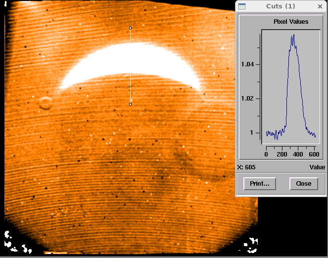 |
This figure shows the ratio between the large scale product from 2016-09-08 and that from 2016-10-02. The prominent pattern has canceled out, the remaining structure (fringe-like ringes and lines) is below 0.5% and the bright ghost shows an intensity of about ~5% of the flat field intensity.
|
The background is stable within the known temperature fluctuations since begin of operations.
Algorithm IFS Detector flat counts
The QC parameter is the median counts in the second (high
exposure time) raw frame of the IFS imaging lamp sequence within the
pixel area: 500 500 1500 1500.
IFS Bad pixel number
QC1_parameters
| FITS key |
QC1 database: table, name |
definition |
class* |
HC_plot** |
more docu |
| QC.NUM.BADPIXELS | sphere_ifs_dflat..qc_num_badpix | number of bad pixel | HC | | [docuSys coming] |
*Class: KPI - instrument performance; HC - instrument health; CAL - calibration quality; ENG - engineering parameter
**There might be more than one. |
Trending
The number of bad pixel, which in this case scales with the un-illuminated reagion of the detector,
is monitored for all lamp flats.
Scoring&thresholds IFS Bad pixel number
The QC paramater is scored. The upper threshold have been set to 120000 pixel
History
- Since 2016-09-15 un-illuminated areas in the lower left and right
corner of the IFS detector flat (all setups) continuously increase,
meaning the vignetted area becomes larger. The fixed pattern (prominent
features) does not move as shown in the product ratio image above. After
an alignmernt on 2016-10-11 the format was adjusted (WH 2016-10-11)
- 2018-06-01: un-illuminated areas in the lower left and right
corner of the IFS detector flat (all setups) continuously increase,
meaning the vignetted area becomes larger (see previous event).
The optics was re-aligned on 2018-06-14.
Algorithm IFS Bad pixel number
The number of pixel, which do not exceed a minimum illumination level are counted.
|
