 mirror sites:
PL (internal link)
HQ
[?]
Quality Control and
Data Processing
SPHERE: IRDIS Background
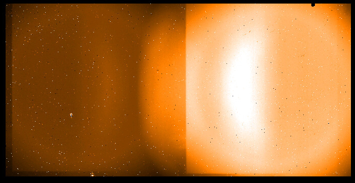
Dark frames are taken with INS1.OPTI1.NAME=CLOSED to measure the detector dark current, while IRDIS background calibration frames are acquired with INS1.OPT1.NAME=OPEN to measure the instrumental background. The background is dependent on the set of used filters:
CPI neutral density filter (IN4.FILT2.NAME = OPEN, or ND_2.0, or ...)  IRDIS background rate
The trending plot shows background rate values for DBI mode only:
The background rate (in ADU/sec) is monitored for the DBI modes only (INS1.OPTI2.NAME != CLEAR). As can be seen on the health check plot , the background in the H-band is stable with about 0.13 ADU/sec (upper left box) and shows a larger scatter for the K-band at 17 ADU/sec (upper right box). The lower right box shows the K-band background when there is a neutral density filter in the CPI (large back and blue symbols). In this configuration the measured background follows the temperature of the neutral density filter. The black, blue and green symbols show the mesred background rate, while the red small symbols show the scaled temperature sensor value and demonstrates the correlation. The following scaling is used for the temperature sensor INS4.TEMP449.VAL located in the common path interface: i T(in the plot) = 1.452 * T - 1.409 The background rate is monitored for the less frequently used modes DPI and LSS, but not for CI mode. Scoring&thresholds IRDIS background rate The background rates are scored for the DBI mode H and K bands without neutral density filter. The background is stable within the known temperature fluctuations since begin of operations. Algorithm IRDIS background rate The pipeline returns the median level of the raw frame cube. The QC script divides this value by DIT. |
|||||||||||||||||||||||||||||||||||||||||||||||||||||||||||||||||||||||||||||||||||||||||||||||||||||||||||||||||||||||||||||||||||||
| |
|||||||||||||||||||||||||||||||||||||||||||||||||||||||||||||||||||||||||||||||||||||||||||||||||||||||||||||||||||||||||||||||||||||
 |
|
||||||||||||||||||||||||||||||||||||||||||||||||||||||||||||||||||||||||||||||||||||||||||||||||||||||||||||||||||||||||||||||||||||
