
AOModes
Contents
- Introduction
- Single Conjugate Adaptive Optics
- Multi-Conjugate Adaptive Optics
- Laser Tomography
- Ground Layer Adaptive Optics
- Multi-Objects Adaptive Optics
- Extreme Adaptive Optics
Introduction
The basic concept of an adaptive optics system is a beam separation between a science imaging field of view and a wavefront sensing path; the adaptive correction is done on the science target that is on-axis. There is one Wavefront Sensor (WFS) controlling (via a real-time computer [RTC]) one Deformable Mirror (DM).
Throughout the '90sthis way to conceive adaptive optics evolved. A multitude of alternate ways of performing an adaptive correction have been imagined. Some of them are used for the AO Facility and have been demonstrated using MAD. This page aims at providing an exhaustive list and explaning the concepts.
In the following figures standard way of illustrating components are used:
- "whitish" cylinders represent the light beam crossing the atmospheric layers as seen by the telescope aperture
- wavy horizontal blue lines represents the wavefront perturbation
- dark red rectangle represents the telescope aperture
- yellow lines symbolize deformable mirror or corrective optics;they are represented as transmissive optics for simplicity
- blue boxes depicts the WFS units
- red rectangle illustrates the RTC (or "WFC" Wave Frontre Constructor)
- lines joining WFS' to WFC to DM's mean that these components function in a closed loop
Single Conjugate Adaptive Optics: SCAO
This is the basic and simplest configuration (Figure 1). A guide star is observedon-axis on the science detector and also used for wavefront sensing.Usually a beamsplitter or dichroic splits the beam between the 2light-paths. Quality of correction or Strehl ratio is limited by the WFC bandwidth (speed of the correction) and the fitting error (number of element of the system i.e. number of actuators of the Deformable mirror).
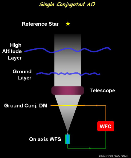 |
| Figure1: Schematic of the simplest AO mode; single conjugate adaptive optics. |
A variant of this technique if the opto-mechanical configuration of the WFS allows it, is to use a different astronomical target for science and for WFS correction. This is used when the science target is too faint or no point-like object (other considerations might be relevant like the optimal way to split light between WFS & science field).In such case, the observation is not limited only by bandwidth and fitting error but also by anisoplanatism (Figure 2). This effect gets more important as the angular distance between science target and guide source increases; the degradation of the correction is due to the fact that the cylinder of atmosphere seen & measured by the WFS doesn'tmatch perfectly the cylinder of atmosphere through which the science target beam propagates.
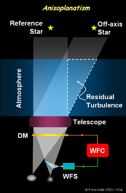 |
| Figure 2: Anisoplanatism effect leading to a degradation of the correction. The turbulence sensed by the WFS doesn't match the turbulence corrected by the DM. |
In order to be able to apply an adaptive correction at any position on the sky and without depending on the presence of a bright natural guide star, laser beacons were used to produce an artificial bright laser guide star (LGS). The science and WFS paths are then separated by a Dichroic. There are basically two types of LGS: Rayleigh and Sodium beacons. Rayleigh beacons are usually green (short wavelength) laser beams and the back scattered light is analysed. Some time synchronisation scheme is required in (time gating of the WFS detectoror/and pulsed laser) in order to sense the proper atmospheric altitudede pending on time delay of the light travel path. Sodium beams use the589 nm Na line to bring in resonance the thin layer (~10 km thick) ofNa at 90 km altitude. Here no particular time scheme is required to analyse the returned beam. There are two fundamental limitations of laser beacons: first they do not provide tilt information (canceled out by the returned path of the beam) and they do not sample the higher layers of the atmosphere known as the "cone effect" (Figure 3).
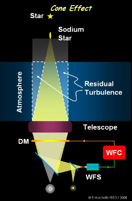 |
| Figure 3:Another degrading effect the so-called cone effect. Again due to a mismatch between the volume of atmosphere sensed with the LGS and the volume corrected for the science target. |
Multi-Conjugate Adaptive Optics: MCAO
In order to overcome the basic limitation of anisoplanatism, the MCAO concept was developed (Figure 4). Indeed, even in the case of SCAO anisoplanatism is also present; it doesn't limit the quality of correction on-axis,but does off-axis. Hence if there are many other scientific targets of interest in the field, the quality of the adaptive correction on them will degrade as their angular distance to the guide source increases. In one word, the basic limitation of SCAO are the very small corrected field of view. It can be only a few arcseconds in the visible up to ~0.5-1 arcmin in the infrared bands (K @ 2.2 micron).
To limit this effect it was imagined to combine several WFS', sensing different guide stars in the field of view, controlling several DM's conjugated to atmospheric layers at different altitude; at least one DM is conjugated to the ground layer (or telescope aperture) since there is usually a large proportion of the turbulence at this altitude. This is a fundamental step because this technique can lead ultimately to large(r) corrected field of view; it then makes a ground observatory with MCAO system almost equivalent to a space telescope (the only remaining limitation being then the spectral windows absorbed by the earth atmosphere). This scheme of adaptive correction has been demonstrated by MAD.
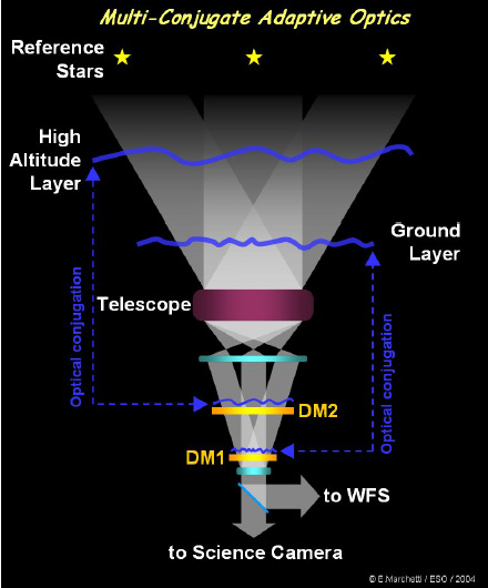 |
| Figure 4: The principle of Multi-Conjugate Adaptive optics. Several WFS' and DM's are combined in order to "optimize" the adaptive correction in a larger field of view. |
There are however several ways of using the WFS's signals to control the DMs. The whole system can be seen as one unit; assume 3 WFS of Nwsubapertures and 2 DMs of Nd actuators, one can build a global interaction matrix of 3Nw lines by 2Ndcolumns. The inversion of this matrix provides the control matrix.
The Star Oriented strategy (Figure 5) is the version of MCAO where the correction is optimized in the direction of each guide stars. Therefore, the correction might not be homogeneous in the whole field of view.
 |
| Figure 5: The Star Oriented version of MCAO. |
In the Layer Oriented scheme (Figure 6) each WFS is associated to a DM and to a given atmospheric layer. The WFS signals from all stars are combined optically and these signals are used to to command a given DM. One has two independent control loops correcting optimally the corresponding atmospheric layer turbulence.
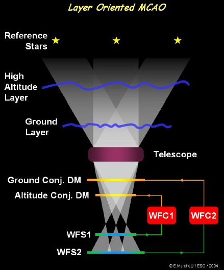 |
| Figure 6: The Layer Oriented version of MCAO. |
For Star oriented MCAO's the number of WFS's must be equal to the number of guide stars; this can lead to a complex opto-mechanical system if several stars are required for the level of correction wished. For the Layer oriented there is a constant number of WFS which can be different than the number of guide stars.
More sophisticated technique can mix in the IM information about the layer structure of the turbulence and optimize consequently the turbulence. The goal is to homogenize the strehl across the field of view or the correction quality by controlling anisoplanetism effects(mismatch between the DM's conjugated altitude and the atmospheric layers dominating the turbulence. This technique is called tomography and is described in the next section.
Laser Tomography: LTAO
In this scheme laser beacons are used in the field of view to provide WF sensing information (Figure 7). The WFS signals are used to assess the turbulence distribution of the atmosphere that is dominant layers and respective amplitude of turbulence. This information is used to optimize the correction on-axis. In this scheme, the cone effect is somewhat "kept under control". The system performs at the level of a SCAO system with the difference that no bright natural star is required and the corrected field of view is small. This mode of correction will be used for the GALACSI Narrow Field of View. MAD has also demonstrated this mode of correction
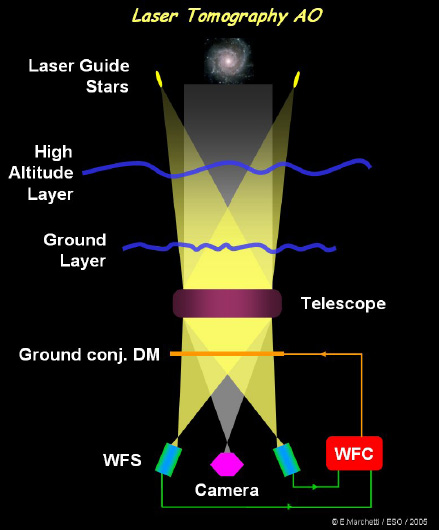 |
| Figure 7: Laser Tomography used to obtain a high Strehl (or correction) on-axis from the signal senses on LGS around the science target. |
Ground Layer Adaptive Optics: GLAO
Ground Layer Adaptive Optics is a "seeing enhancement" technique (Figure8).Several WFS and one DM are at play. The guide sources are distributed in a relatively large FOV and the WFS signals are averaged to provide a command vector to the DM. The result is a reduction of the FWHM of the stars or light concentration in the FOV. In the case of GRAAL, a gain of 2 in the energy concentration of the the star (2 times more ensquared energy in the 0.1" pixels) is obtained in a 7 arcmin field of view in K-band.This technique is particularly efficient if the turbulence is concentrated in the ground layer. Note that this mode is also used for GALACSI Wide Field of View mode; the gain is similar, that is x2 in ensquared energy but for a smaller FOV, 1 arcmin, since the observed wavelength is shorter (700 nm).
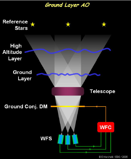 |
| Figure 8: Ground Layer Adaptive Optics. For improved image quality in a very large field of view. |
Multi-Objects Adaptive Optics: MOAO
A very important observation technique in astronomy is called MOS; Multiple Objects Spectroscopy. It consists in inserting several apertures in a large FOV in order to obtain spectra of several objects.It is therefore used for FOV crowded with astronomical targets like star clusters or galaxy clusters to study the properties of individual objects.
Due to the large FOV required for such observation, AO has failed to provide an efficient correction for this technique. Lately, a technique called MOAO (Figure 10) has been imagined. It consists in providing correction noton the complete FOV but in local areas in a very large FOV(several arcmin). The astronomer must identify guide sources in close proximity to the science target (see Figure 9). Several reference sources provide WFS signals for correction on a given science target. Small "arms" are inserted in the FOV to pick-up the light of the reference sources and feed them to the WFS, on one hand, and to insert a small DM in front of each science targets to correct the beam on the other.
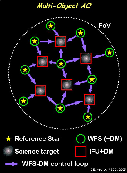 |
| Figure 9: Example of configuration of the light-paths in the telescope focal plane. The red squares represent the images to be corrected by AO and the green circles eventual guide stars in the fields. The purple arrows indicate that several (and which ones) guide stars WFS signals can be used for a given science target. |
The separation of the beams is complete and therefore the systems work in open loop. In other words the WFS beam is NOT corrected since the DMs provide correction only for the science targets paths. WFS therefore sees the full amplitude of turbulence and must be designed to have a large dynamical range and be linear sensors as much as possible.
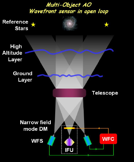 |
| Figure 10: Open loop scheme of MOAO. |
A slight improvement to this Open Loop scheme can be brought by the addition of DM's also in the WFS paths (Figure 11). However, there are still no WFS on the science paths as such and therefore the science DM still funtion in Open Loop. Nevertheless, the amplitude of the turbulence on the WFS 'is reduced and this relaxes the requirement for large dynamic and highly linear behavior of the WFS's.
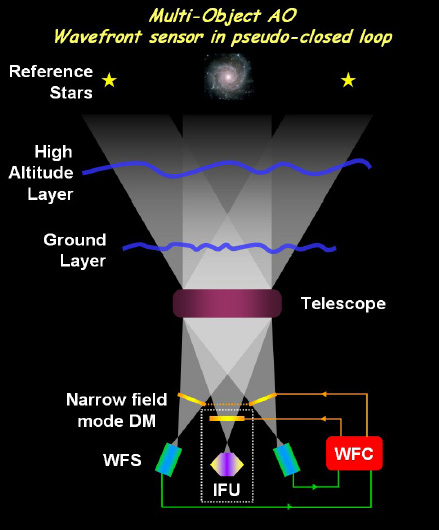 |
| Figure 11: Pseudo-Closed loop scheme of MOAO. |
A somewhat similar strategy can be adopted by the use of GLAO correction. As illustrated on the Figure 12 and if a single DM is available to correct the whole FOV (the AO Facility could use suchscheme thanks to the Adaptive Secondary mirror), the turbulence in thecomplete FOV can be reduced (gain of ~2 in ensquared energy). Thescience DM still funtion in Open Loop but the amplitude of theturbulence on the WFS' is reduced by action of the GLAO correction onthe whole FOV.
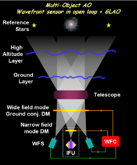 |
| Figure 12: A combination of GLAO and open-loop WFS scheme for MOAO. |
The latter technique combined the 2 methods described above (Figure13).
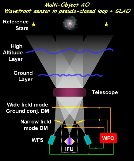 |
| Figure 13: The most complex MOAO scheme; WFS in pseudo-closed loop plus GLAO correction. |
Extreme Adaptive Optics; XAO
This technique requires a configuration similar to the SCAO; it therefore provides high strehl correction on-axis and a small corrected FOV due to anisoplanetism. Only it goes further; strehl correction is extremely high (Strehl values in excess of 90% at the wavelength of interest). Due to the very high spatial frequencies corrected in the wavefront, anisoplanetism is still stronger and the corrected FOV is for all practical purpose limited to on-axis, on the corrected object.
This technique requires a high degree of care to minimize all possible causes of errors and mis-alignment of the optical beam, in particular pupil alignment on the DM. A thorough error budget must be develop to keep the residual WFE (wavefront error) of the system to a minimum.
Coronography is often coupled to this technique as an important application is the search for faint companions around bright stars (the latter being used as reference source) and in particular the search for planets.
What's new?
Check for the next lunch Talk.
Quick Links
- Home
- Adaptive Optics group expertise and activities
- Adaptive Optics Systems
- Adaptive Optics Technologies
- AO lunch talks
- Other useful links
Special Event: 20 years of Adaptive Optics at ESO
Contact Us