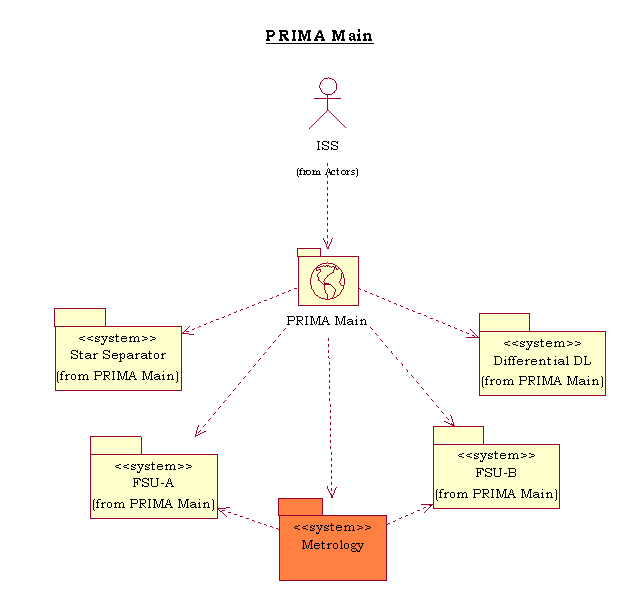
The PRIMA Facility is composed of 5 systems:
These 5 systems are controlled by the PRIMA Main Control Software deployed on the PRIMA WS.
![]() PRIMA System Main Use-Case diagram
PRIMA System Main Use-Case diagram
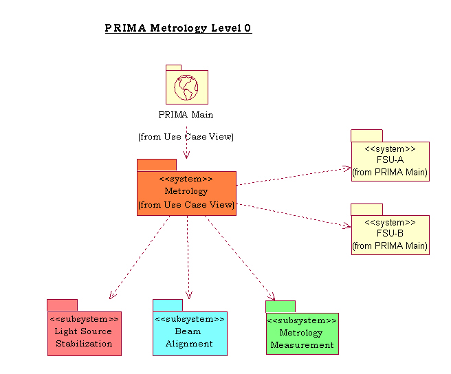
The system under study is the PRIMA Metrology System. It is considered as a System per se since it can be seen as an actor of the PRIMA Main Control Software.
This document describes all the Use Cases for the PRIMA Metrology Control Software extracted from the requirements in the following documents:
These requirements have been checked with the general VLT and VLTI requirements.
In this Requirements View, the system must be considered as a black box and no attention must be paid to the internal system architecture. External Actors interact with the system as a whole and interactions between system components are not important.
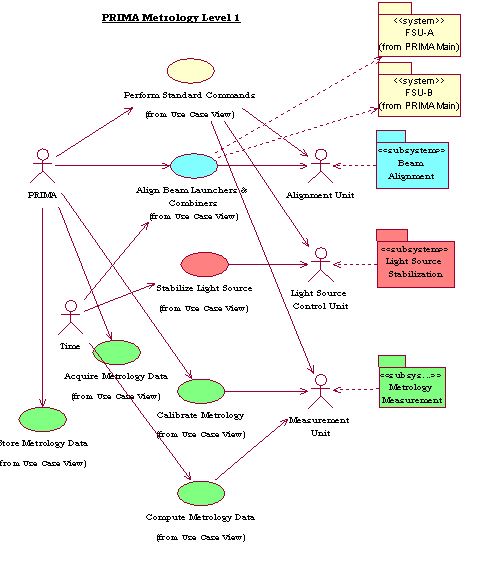
In the following sections, all Use Cases are listed, grouped according to their function. During design, Use Cases are assigned to software packages, but at requirement level we always consider the whole system as a black box. Nevertheless, the functional groups typically map very well with packages, since they correspond in most cases to the control of specific subsystems.
Some Collaboration Cases are listed, since they map system requirements, even though they are not directly seen by primary external Actors.
The interaction of human users with the system will take place via command interfaces and graphical user interfaces. In this document the type of user interaction is not specified, unless explicitly requested by the mapped requirements.
The general functions are used to command the PRIMA Metrology
System as a whole and to provide information regarding its global
operational state.
They provide basically the following two services:
The PRIMA Metrology Control System global status is based on the status of sub-systems based on current operational conditions.
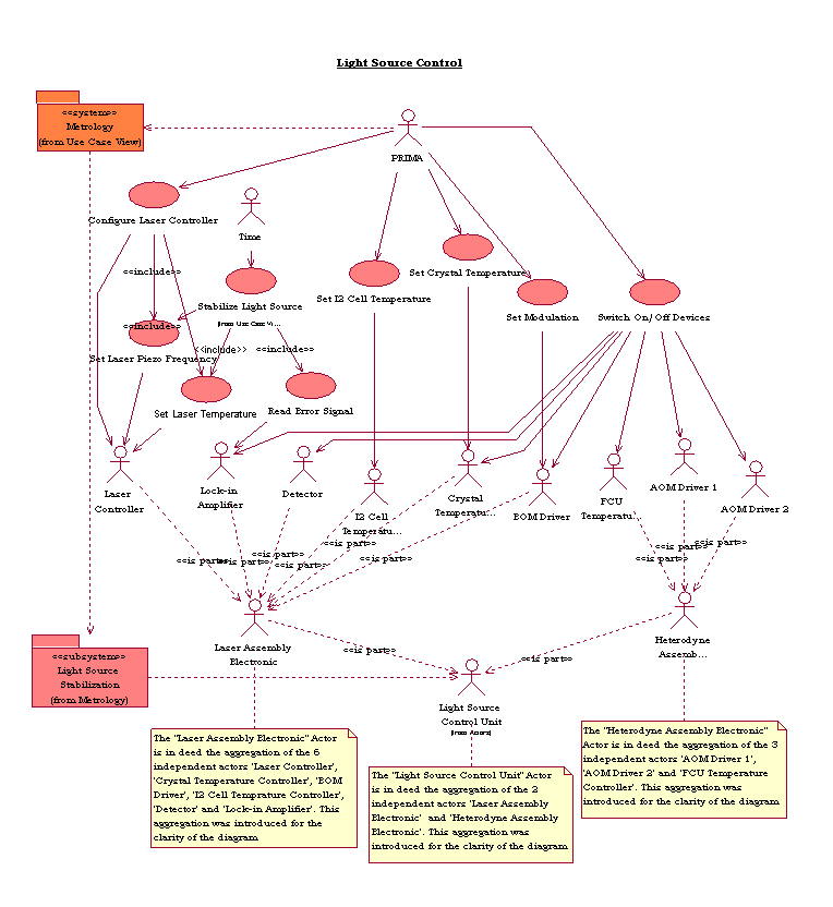
![]() Light Source Control Use-Case diagram
Light Source Control Use-Case diagram
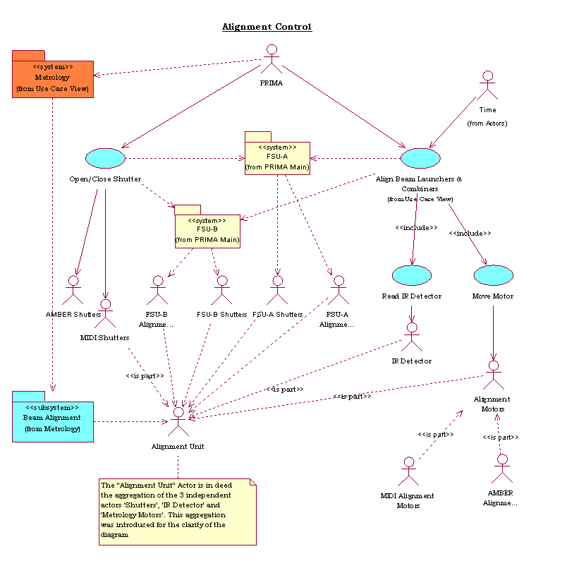
![]() Beam Alignement Use-Case diagram
Beam Alignement Use-Case diagram
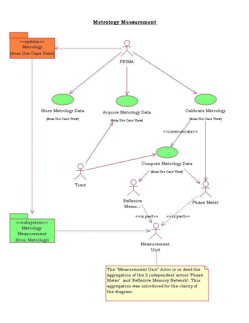
![]() Metrology Measurement Use-Case diagram
Metrology Measurement Use-Case diagram
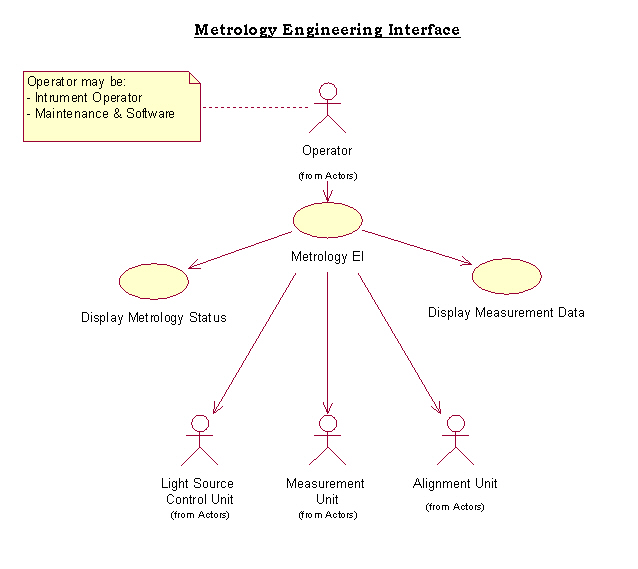
![]() PRIMA Metrology GUI Use-Case diagram
PRIMA Metrology GUI Use-Case diagram
This sub-section describes some Collaboration Cases that are important at the level of requirement specification.
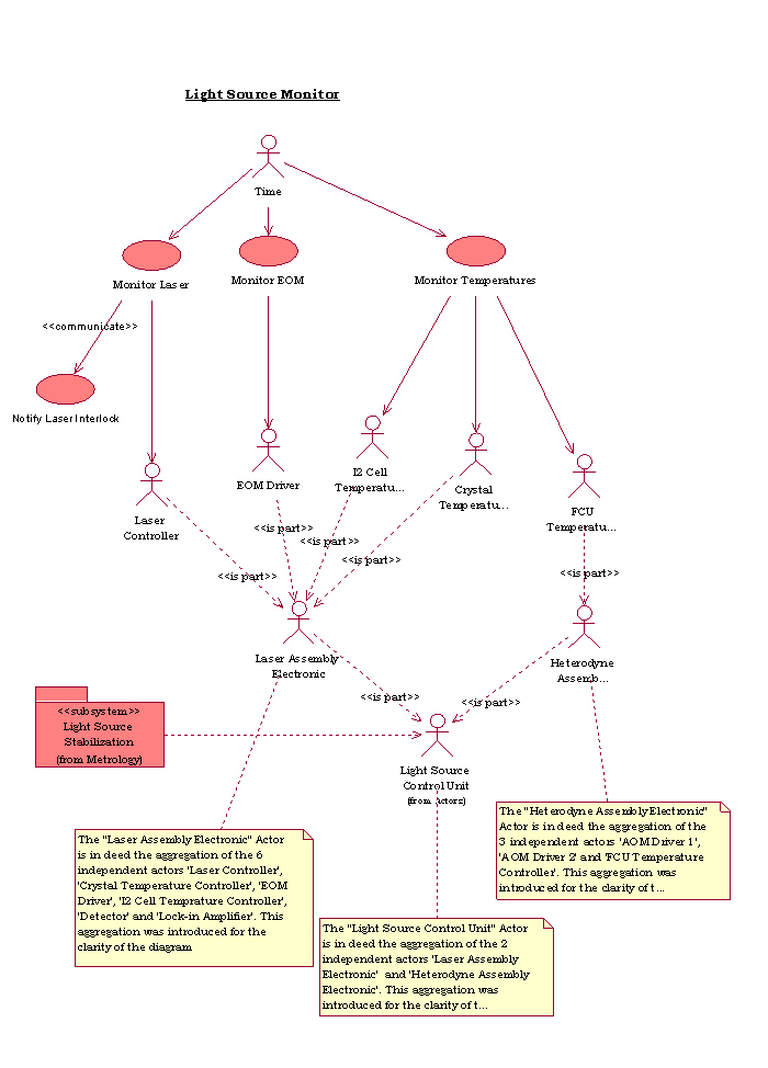
![]() Light Source Monitor Use-Case diagram
Light Source Monitor Use-Case diagram
[ ESO | VLT software | VLT OOWG ]
Last modified: Wed Feb 26 11:31:23 MET 2003