Quality Control and
Data Processing
|
NACO: Flat fields and calibration lamps
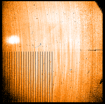
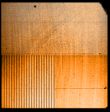
The LAMP FLAT frames are obtained within the NACO daytime calibrations every night the science data are taken. Each LAMP FLAT consists of 6 raw frames (3 pairs lampON/lampOFF) obtained with the instrumental setup matching the one used for science observations. Only the short wavelength filters are supported (J, H K regime). For the long wavelength (L-band) the "flats on sky" are taken. The LAMP FLATs are supplied for both imaging and spectroscopy but only the imaging lamp flats are processed by the NACO pipeline. Example master flats are from 2016-11-26
 Fixed pattern noise
Normalized master lamp flats contain the pixel-to-pixel gain variations, (the gain map, or fixed pattern noise) as an instrumental signature which is removed from the science observation by dividing the dark subtracted science frame by the master lamp flat.
The term noise in 'fixed pattern noise' is misleading, because FPN is not defined for a single pixel, while detector read noise and photon noise are defined for a single pixel. In a well exposed single flat frame and even better in a frame combined of many flats with a high sign-to-noise ratio, the signal between different pixels represent the difference of responses or gains. A robust rms over a larger area of detector pixels is called the fixed pattern noise, or the RMS of the gain map. The fixed pattern noise is sensitive to illumination gradients, vignetting, persistence and light contamination. The left trending plot covers the setup DoubleCorr, HighDensity, filters J, H, Ks, camera S13 and DIT=15sec, the right plot covers setups FowlerNsamp HighSensitivity, filter J, H, Ks, camera S13 and DIT=15sec..
Scoring&thresholds Fixed pattern noise the fixed pattern noise derived from the lamp flats is not scored. After the detmon recipe has been put in operations in 2016, the FPN derived from lamp flats serves only as a fall back solution. While the FPN derived from the detmon recipe covers four read modes, camera=S27, and filter=NB_1.64, the lamp flat FPN covers a larger variety of cameras. The pipeline delivered lam flat QC.FPNOISE parameter is divided by the raw frame counts to become insensitive to the actual counts in the flat.
Flux of the flat field lamp
The lamp flux, measured in ADU/sec from the difference frames: LAMP=ON minus LAMP=OFF, is to monitor aging effect of the flat field lamp. The flat field lamp is used for filters the wavelength bands J, H and K.
The lamp flux is monitored for two read modes, three broad band filters and two cameras separately. Scoring&thresholds Flux of the flat field lamp The lamp flux [ADU/sec] is not scored. The counts [ADU] in the flats are scored instead. Before 2015, another detector was in operation. Algorithm Flux of the flat field lamp Median flux of the difference between the first lamp ON and the first lamp OFF raw frames of the lampflat, divided by DIT; calculated by the naco_img_lampflat recipe.
Counts in the flat frames
The flat counts are monitored for two read modes, three broad band filters and two cameras separately. Scoring&thresholds Counts in the flat frames The flat counts are scored to obtain the quality of the calibration product. The lower threshold is set to 3000 ADU, that the master flat, based on three raw frames with 9000 ADU, corresponds to a signal-to-noise ratio of 95. Most of the flats show about 4000 ADU resulting in a SN-ratio of ~100. According to the detmon results the non-linearity is about 18% at 8000 ADU for DoubleCorr and 14% at 3000 ADU for FowlerNsamp. Operational thresholds of 6000 ADU and 3000 ADU flags flats with more than ~15% non-linearity. Before 2015, another detector was in operation. Algorithm Counts in the flat frames Median counts of the first raw flat of the sequence.
Illumination gradient
Imperfect alignment of the calibration unit and the calibration path can result in an inhomogeneous illumination of the detector. The illumination gradient, as a first order deviation from a balanced illumination for lamp flat fields is parameterized and monitored.
Introduced in 2015 after some issues with the calibration unit, this parameter measures the large scale gradient over the field of view in two directions. The gradient is stable since then within each read mode and optical setup. Scoring&thresholds Illumination gradient The gradient of the flat field is scored. The thresholds are set to +-5%. Before 2015, another detector was in operation. Algorithm Illumination gradient To measure the illumination gradient over the FOV, four pixel-windows have been defined on the master lamp flat product, each one 100x100 large, and with a distance of about 100 pixel from the edge of the chip with centers at
Based on these four windows one flux gradient in x and one in y is calculated. The flux gradients are normalized to the size of the FOV (Delta x = 1024 pixel). E.g. xgradient = -0.2 means, that the counts are 20% less on the right rim than on the left rim of the detector. The gradient monitors a symptom, not a cause. Note that the lamp flat FOV illumination gradient is different between detector read modes since of a contamination issue.
Gain (from lamp flats)
Before the detmon template was put in operation in 2016, the detector gain has been derived from lamp flats. Note that the gain derived from the detmon template via the photon transfer curve is much more precise and unbiased.
The lamp flat gain is monitored for two read modes. Scoring&thresholds Gain (from lamp flats) The gain derived from the lamp flats is not scored. The gain is stable. The two detectors which replaced older ones were/are operated with the same gain values. Algorithm Gain (from lamp flats) The pipeline subtracts two raw flats of the same exposure level to eliminate fixed pattern noise (gain map contributions). The residual statistical noise is composed of mainly photon noise and smaller contributions of detector read noise. The gain is derived numerically from the counts and the photon noise.
|
||||||||||||||||||||||||||||||||||||||||||||||||||||||||||||||||||||||||||||||||||||||||||||||||||||||||||||||||||||||||||||||||||||||||||||||||||||||||||||||||||||||||||||||||||||||||||||||||||||||||||||||||||||||||||||||||||||||||||||||||||||||||||||||||||||||||||||||||||||||||||||||||||||||||||||||||||||||||||||||||||||||||||||||||||||||||||||||||||||||||||||||||||||||||||||||||||||||||||||||||||||||||||||||||||||||||||||||||||||||||||||||||||||||||||||||||||||||||||||||||||||||||||||||||||||||||||||||||||||||||||||||||||||||||||||||||||||||||||||||||||||||||||||||||||||||||||||||||||||||||||||||||||||||||||||||||||||||||||||||||||||||||||||||||||||||||||||||||||||||||||||||||||||||||||||||||||||||||||||||||||||||||||||||
| |
|||||||||||||||||||||||||||||||||||||||||||||||||||||||||||||||||||||||||||||||||||||||||||||||||||||||||||||||||||||||||||||||||||||||||||||||||||||||||||||||||||||||||||||||||||||||||||||||||||||||||||||||||||||||||||||||||||||||||||||||||||||||||||||||||||||||||||||||||||||||||||||||||||||||||||||||||||||||||||||||||||||||||||||||||||||||||||||||||||||||||||||||||||||||||||||||||||||||||||||||||||||||||||||||||||||||||||||||||||||||||||||||||||||||||||||||||||||||||||||||||||||||||||||||||||||||||||||||||||||||||||||||||||||||||||||||||||||||||||||||||||||||||||||||||||||||||||||||||||||||||||||||||||||||||||||||||||||||||||||||||||||||||||||||||||||||||||||||||||||||||||||||||||||||||||||||||||||||||||||||||||||||||||||||
 |
|
||||||||||||||||||||||||||||||||||||||||||||||||||||||||||||||||||||||||||||||||||||||||||||||||||||||||||||||||||||||||||||||||||||||||||||||||||||||||||||||||||||||||||||||||||||||||||||||||||||||||||||||||||||||||||||||||||||||||||||||||||||||||||||||||||||||||||||||||||||||||||||||||||||||||||||||||||||||||||||||||||||||||||||||||||||||||||||||||||||||||||||||||||||||||||||||||||||||||||||||||||||||||||||||||||||||||||||||||||||||||||||||||||||||||||||||||||||||||||||||||||||||||||||||||||||||||||||||||||||||||||||||||||||||||||||||||||||||||||||||||||||||||||||||||||||||||||||||||||||||||||||||||||||||||||||||||||||||||||||||||||||||||||||||||||||||||||||||||||||||||||||||||||||||||||||||||||||||||||||||||||||||||||||||