
MIDI Instrument Characteristics
Basic facts
| Status | Open for VM and SM |
| Built by: | The MIDI Consortium |
| P.I. | Christoph Leinert |
| Instrument Scientist (Garching) | Marcus Schoeller |
| Instrument Scientist (Paranal) | Thomas Rivinius |
| Location | |
| "First fringes" | December 2002 |
| Number of guaranteed nights for the MIDI Consortium | 30x2 UTs + a fraction of the time available on the ATs. Over 6/8 years respectively. |
General description
MIDI is built around a Michelson-type (half-reflecting plate) two-beam optical recombiner. It uses as light-collectors either two VLT unit-telescopes(UTs), or in the future two VLT auxiliary-telescopes(ATs), and the whole VLTI infrastructure (delay-lines, M16, switch yard,beam-compressors, fringe tracker). The UTs are equipped with MACAO adaptive optics (limiting magnitude for guiding: V=17), the ATs with STRAP tip-tilt correctors (limiting magnitude for guiding: V=13.5).
Due to thermal radiation from the environment, most of the optics is enclosed in a cryostat cooled at 40 K (actually, 35 K can be reached thanks to the cold-head of the helium closed-cycle cooler of MIDI). The array detector of MIDI is cooled at 10 K. Thermal radiation from background and stray-light are reduced thanks to the pupil-stops inside the cryostat. The beam-combination is done close to the pupil plane while the signal is detected in an image plane. The light path within MIDI can be summarized as follows (figure below): the collimated beams from the telescopes, reduced to 18 mm by the VLTI Beam-Compressors. To generate interferograms, the difference of optical path length between the beams is time-modulated by dihedral reflectors mounted on piezoelectric transducers (PZTs). Each PZT travel, generating one interferogram, is called a "scan".
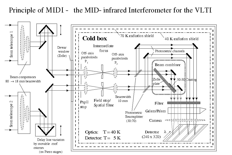
Principle of MIDI (click on the image to get it larger)
The optics of MIDI is not fully reflective (gold is used as coating for mirrors of MIDI because of its high reflection factor in theinfrared), but also refractive. The refractive components of MIDI are made of germanium and zinc-selenide (ZnSe), a material which has the property to be transparent in N-band, but has a high refraction index(2.39 at 10 µm and T=50 K), requiring anti-reflection coatings whenever this is possible,
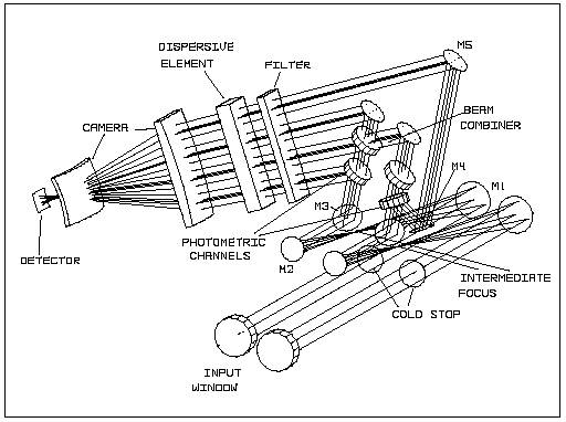
Optical design of MIDI (click on the image to get it larger)
After passing through the pupil-stops, the beams are focused on the field-stops. These stops can be pinholes for spatial filtering, orslits (if spectroscopic mode is used). Full-field imaging is also possible. After re-collimation, part of the beam can be sampled by30/70 ZnSe beam splitters to obtain the photometry of the source (if this mode has been selected). The remaining part of the beams are combined thanks to a 50/50 ZnSe plate (acting also as achromatism-compensation plate). The two interferometric beams (and optionally the two photometric beams) are spectrally filtered,dispersed by a grism or a prism (if spectroscopic mode has been selected), and focused by the germanium "camera" element on the detector plane. This detector is a Raytheon Si:As (IBC) array, and is characterized by a fast frame readout, in order to deal with the atmospheric coherence time.
Detector characteristics
| Resolution | 320 x 240 pixels |
| Sampling by camera on sky (UTs) | 3 pixels per lambda/D (=0.26 arcsec on sky with UTs, =1.15 arcsec on sky with ATs) in image acquisition and prism spectro setups --- 2 pixels per lambda/D along y, 1 pixel per lambda/D along x (dispersion axis) in grism spectro setup |
| Readout mode | Integrate-Then-Read |
| Maximum frame rate (full frame) | 160 Hz |
| Minimum integration time | 0.2 ms |
| RMS readout noise | 850 e- |
| Windowing | Row selection by specific clocking patterns Column selection by software real-time processing |
| Format of generated exposure files | FITS tables |
Acquisition
Beam overlap leading to interference is normally performed by the IRIS sub-system of VLTI (i.e., the IR guider located in the VLTI laboratory). Otherwise, it is ensured by the"acquisition" procedure of MIDI. MIDI is setup to provide images from the beams with a maximum field-of-view of 2 arcsec. The scale is 84milli-arcsec per pixel (if telescopes are the UTs) or 0.37 arcsec per pixel (if telescope are the ATs). In any case, the size of an Airy disk(lambda/D) is 3 pixels. For the acquisition, the user can select any filter (see "Appendices" below).
Fringe exposures
After combination, beams are dispersed along the horizontal axis of the detector. The dispersion is done either by a NaCl prism (R=30) or a KRS5 grism (R=230). Fringe are recorded while modulating the OPD. Typical values are:
| Number of detector frames per fringe | 5 |
| Number of fringes per scan | 8 |
| Number of useful scans per exposure | 180 |
Alternatively, the "fringe/astrometry" mode can be used. In this mode,there is no spectral dispersion, and the scan length is longer (14fringes). This mode allows to detect fringes from several sources that are very close.
No chopping is used for the fringe exposure if the HIGH_SENS beam combiner is used. Thanks to the property of the half-reflecting combiner plate of MIDI, the fringes between the two interferometric channels are pi phase-shifted. Since the background noise is extremely correlated between the two channels, subtraction of the signals from the interferometric channels in a detector frame allows to remove the background noise and to enhance the interferometric signal (fringes).
Photometry exposures
If the HIGH_SENS beam combiner is used, "photometry" exposures are taken after the fringe exposures in order to derivate the raw visibility from the fringe amplitude. Photometry exposures are taken with the same instrument setup as for the fringe exposure, but only one beam at a time feeds MIDI. Hence, photometry exposures actually contain spectrographic information. Chopping (typically at 2 Hz) is used to take the photometry exposures. Typically, 2500 detector frames are taken for each photometry exposure.
If the SCI_PHOT beam combiner is used, one-beam-only exposures similar to photometry exposures are taken after the fringe exposure.They can be used to correct the photometric channels of the SCI_PHOT beam combiner.