
Instrument Description
| A full description of the VISTA telescope and the instrument is given in the VIRCAM @ VISTA user manual and summarized on this page later. We refer as well to the excellent WEB pages provided by the VISTA consortium, from where we have already extracted most of the content of the other VISTA pages on the ESO domain. | 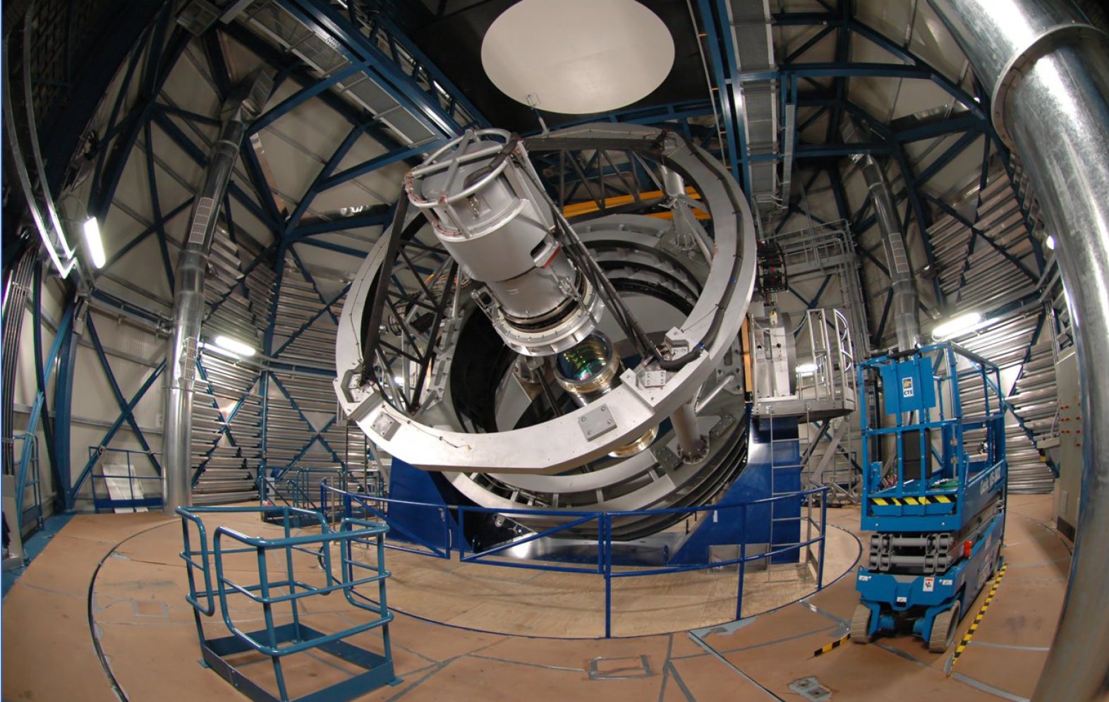 |
Filters and Focal Field Geometry
The filter wheel is the only moving part in the camera. It has seven slots for scientific filters, and one more position reserved for a SUNBLIND (i.e.closed or dark) filter. Each filter is a set of sixteen pieces, one for ach detector, mounted on a tray.
Currently, the camera carries a complement of Z, Y, J, H, Ks,NB980, and NB118 filters. Note that the NB980 position actually holds two subsets of filters - NB980 and NB990, - each covering eight positions. So,to obtain full coverage with these two NB filters the survey area has to be observed twice, with rotator at two complementary positions separatedby 180 deg.
The list of available filters is given in the table below, followed by a plot with the filter transmission curves, the detector quantum efficiency curves, and a theoretical model for the atmospheric transmission for various airmasses and water vapor content of the atmosphere.
| Filter | Wavelength | FHWM | Comment |
| micron | micron | ||
| Z | 0.88 | 0.12 | in camera |
| Y | 1.02 | 0.10 | in camera |
| J | 1.25 | 0.18 | in camera |
| H | 1.65 | 0.30 | in camera |
| Ks | 2.15 | 0.30 | in camera |
| NB980 | 0.98 | 0.01 | in camera, sharing a slot with NB990 |
| NB990 | 0.99 | 0.01 | in camera, sharing a slot with NB980 |
| NB118 | 1.18 | 0.01 | in camera |
A tar file with all curves shown in this plot in machine readable form is available here.
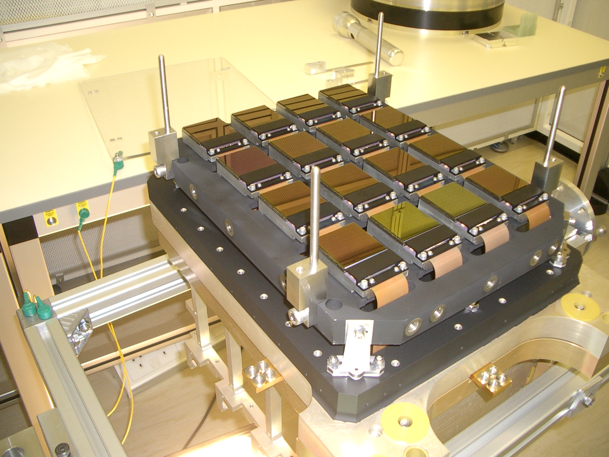
The sixteen 2048x2048 pixel IR detectors (Raytheon VIRGO HgCdTe 0.84-2.5 micron) in the camera are not but table and are arranged as in the following figures which shows a diagram of the focal plane as would be seen looking directly down the camera body (down the Z-axis which on the telescope points towards the sky). On the sky (in the default instrument rotator position) +Y corresponds to N, and +X to West:
 |
|
A single Integration of length DIT secs (or a co-added series of these known as an Exposure) produces a sparsely sampled image of the sky known as a "Pawprint". The area of sky covered by the pixels of a "pawprint" is 0.6 deg2. Full almost uniform sky coverage of a "tile" of 1.501 deg2 canbe achieved with six "pawprints", offset by ±47.5% in y at two respective x-positions offset by95% of the detector size. Any sky position of a "tile" will fall at least on two of these six pawprints.
Instrument Performance
The instrument performance is summarized in the following table:
| pixel scale | 0.34 arcsecs/ pxl |
| best image quality achieved | 0.6 arcsecs including seeing, optics and sampling |
| estimated image quality | Paranal seeing convolved with the instrument PSF of 0.51 arcseconds |
| image distortion | <15%> |
| photometric calibration | +-2% RMS in respect to 2MASS in J,H,Ks |
| photometric calibration | +-2% RMS internally |
| sky concentration/ illumination | <5% absolute, can be corrected down to <2% |
| detector | 16 Raytheon VIRGO HgCdTe arrays, sensitive over 0.84 to 2.5 micron, high quantum efficiency (click here for the QE curve), large number of hot pixels, some dead areas on detector 1 |
The system characterization and the optimization of the calibration strategycontinue during the operation phase.