VIMOS MOS Spectral Formats
MOS Spectral Formats Plots
- LR-Red grism
- LR-Blue grism
- MR grism
- HR-Red grism, slit at center
- HR-Red grism, slit at +4.0'
- HR-Red grism, slit at -4.0'
- HR-Orange grism, slit at center
- HR-Orange grism, slit at +4.0'
- HR-Orange grism, slit at -4.0'
- HR-Blue grism, slit at center
- HR-Blue grism, slit at +4.0'
- HR-Blue grism, slit at -4.0'
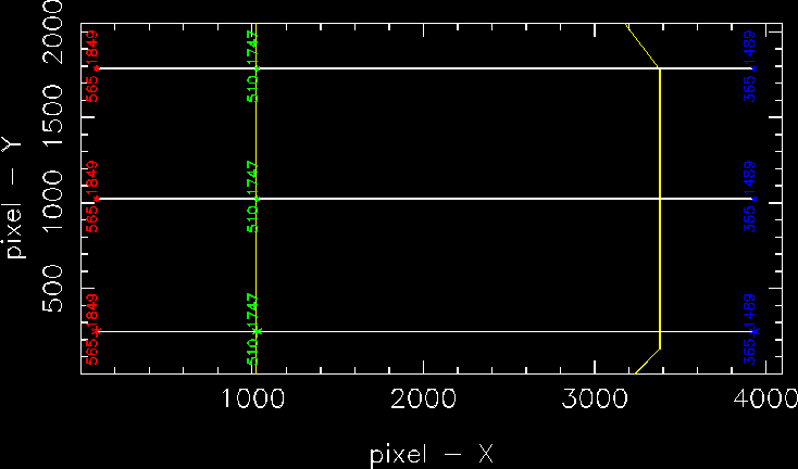
The following figures illustrate the MOS spectral formats.In yellow is indicated the edge of the imaging field of view.The start and end wavelengths are indicated (in nm) belowthe lines symbolizing the spectra, and the correspondingspectral resolutions are indicated above the lines. 3 layersof spectra are shown for illustration. The dots indicatethe object/slit positions.
LR-Red grism
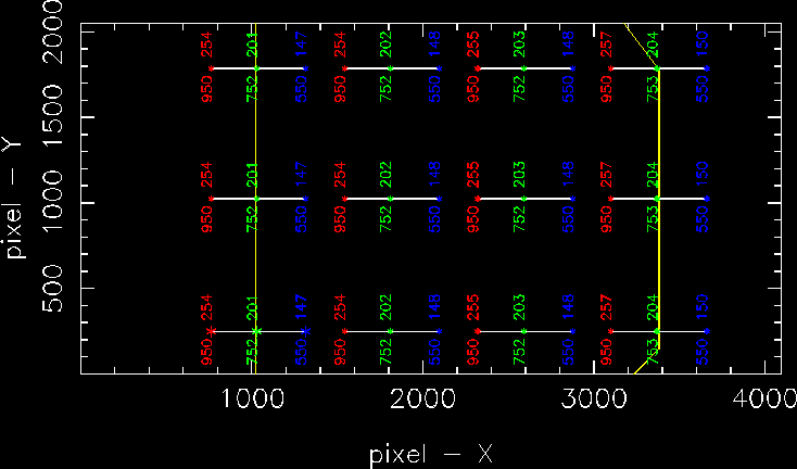
LR-Blue grism
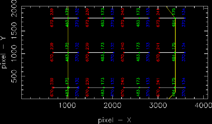
MR grism
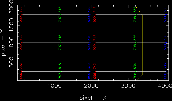
HR-Red grism, slit at center
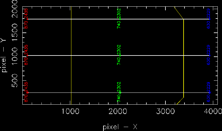
HR-Red grism, slit at +4.0'
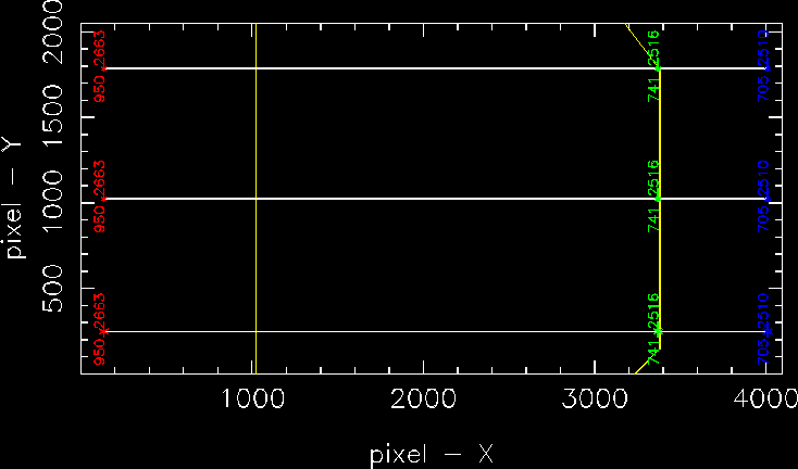
HR-Red grism, slit at -4.0'
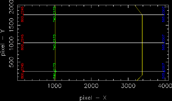
HR-Orange grism, slit at center
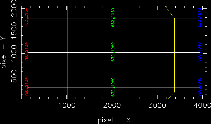
HR-Orange grism, slit at +4.0'
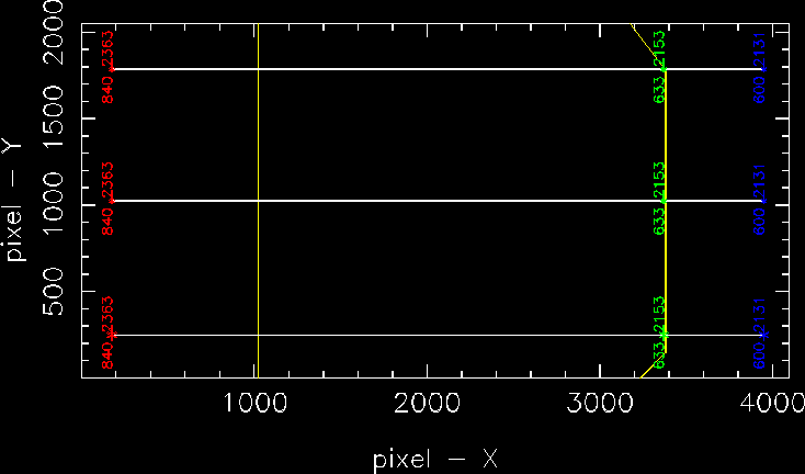
HR-Orange grism, slit at -4.0
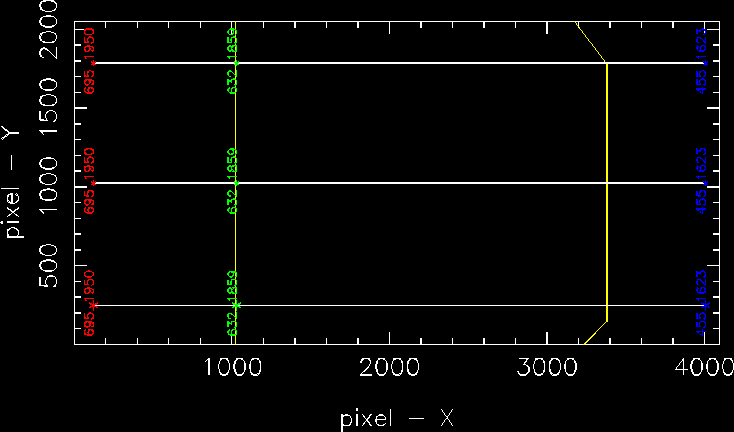
HR-Blue grism, slit at center

HR-Blue grism, slit at +4.0'
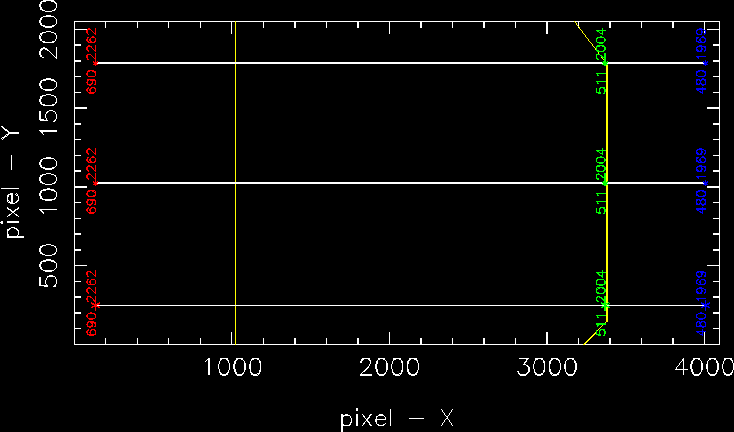
HR-Blue grism, slit at -4.0'
