
SPARTA
Contents
Introduction
ESO has started several projects to provide the four Very Large Telescope (VLT) telescopes with new state-of-the-artinstruments to replace some of the existing ones. These new instruments are collectively called "second generation VLTinstrumentation" and some will be equipped with Adaptive Optics (AO) facilities. The core component of any AOsystem is the Real Time Computer (RTC) which measures the incoming wave-front aberrations by means of a sensor andcorrects for them by means of a deformable mirror. The requirements that this new generation of instrumentation poseson the Adaptive Optics facilities are challenging, in particular to the real-time computer.
At the same time ESO is investigating the next generation of giant telescopes where the Adaptive Optics system, afundamental facility of the telescope, will have to face even harder requirements.
Currently no single-board computer is capable of processing the amount of real-time data required to run these AOsystems. Extreme AO (XAO), Multi-conjugate AO (MCAO) or simply Multi-Target Ground Layer Correctors willrequire about one thousand of actuators for 8m class telescopes like the VLT running at a Kilohertz rate or more. Evenmore actuators and higher speed will be needed for the E-ELT.
The Adaptive Optics Real Time Computer has to be based on multi-processor multi-board computers in order to achievethe required computational power. The complexity of each of these systems and their number raised concerns about thecomplexity of their development, their reliability and their maintenance. Individual efforts aimed at developing differentcustom systems were simply unaffordable not only for the duplication of the design and development effort to buildsimilar products for different systems, but also the amount of resources required to test, maintain and upgrade systemswhich are different in spite to being similar.
The selected solution was a common standard platform that could achieve all the goals of the AO systems for the secondgeneration instrumentation and be capable of targeting the simplest AO systems for E-ELT.This platform, named SPARTA for Standard Platform for Adaptive optics Real Time Applications, provides both ahardware and software common infrastructure in which all the previously mentioned applications can run.ESO's experience of previous Adaptive Optics systems delivered to the Paranal Observatory shows that the corefunctionality of each AO system is limited to about the 20% of the developed software, while the remaining 80%constitutes the infrastructure that performs the same tasks, but in a different way because it has been developed fordifferent systems. It is therefore possible to develop a common software infrastructure that covers 80% of the application needs and is developed and maintained only once for all systems. A common development means also higher quality andreliability since the same code is tested multiple times in the various systems where it is installed.However this becomes possible only if the hardware is standardized as well, in order for the software to run alwayswithin the same platform. This choice became the critical choice for SPARTA. The standard hardware platform had to bescalable to accommodate different needs of the different projects, easily maintainable and upgradeable to follow thetechnological evolution as much as possible, had to provide a powerful development environment to make thedevelopment easy and the final product reliable, and be easy to use strictly following standard operational scenariosdefined by the observatory.
The first requirement, scalability, has been achieved through modularity: SPARTA can be run with a variable number ofcomputational boards.
The second requirement, maintainability, has been fulfilled through the use of Commercial Off The Shelf (COTS)components that are easier to procure and repair than custom developed hardware. COTS components help also in termsof reliability since these are components used in other projects and other companies and so better tested than a customcomponent specifically developed for a single project.
The third requirement, upgradeability, is also fulfilled by the use of COTS products: in many cases it could be true that acustom development can achieve better performance or better integration than a collection of COTS elements. But COTSelements are faster in following the technological evolution and quickly surpass the custom development. In turns, thecustom development requires a heavy investment to benefit from the same technological evolution, since normally thisinvolves restarting the complete design / development / test process.
The fourth requirement, a rich development environment, has been met by using industry standard environments(including operating systems) that are widely used and thus feature a large portfolio of tools.Finally, usability can be achieved by capitalizing on the previous experience and by collaborating with the observatorypersonnel since the early stages of design.
The final result of this project is not only a powerful standard real-time computer for adaptive optics applications, butalso a platform for high-performance parallel computing with fast I/O. The software toolkit designed to fulfill AOrelatedrequirements, in its building blocks can also be used for other applications.
Overview
The aim of the SPARTA project is to provide a standard platform to build adaptive optics real-time computers based onthe requirements of its client projects. SPARTA is not an AO RTC, but provides the tools to build one. Therefore,SPARTA provides the following components:
- Interface definitions:
- External interfaces to connect to sensors (ESO NGC and Andor iXon supported) and actuators (ESO-definedCODE interface)
- Internal interfaces to interconnect the different HW components
- Test tools that can be used to extensively test the platform and its instances at various interface levels
- Hardware components to build the system
- A Software framework that provides the functionality which is common to all AO systems (e.g. datacommunication, configuration, storage, math, etc.)
The SPARTA software executes over a number of different platforms depending upon the performance requirementswhich have to be met, these platforms are:
- A low latency real-time processing pipeline known as the RTC box
- A Linux co-processing cluster
- A standard ESO Instrument workstation
Figure 1 shows a schematic representation of the SPARTA components and the platform in which they run.
 |
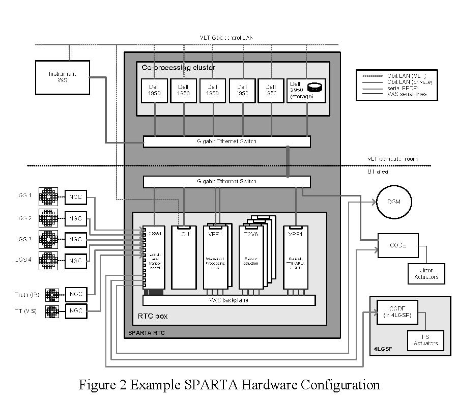
The RTC box handles all tasks directly involvedin the hard real time low latency AO controlloop; acquisition of wavefront sensor data,reconstruction of the incoming wavefront andcontrol of the final mirror actuator positions. TheRTC box is based on a 19" VXS system hostingseveral specialized embedded computing boards.As well as implementing the core AO loop theRTC box continuously sends sensor and actuatordata to the co-processing cluster for additionalprocessing. All wavefront sensors and actuatorsare directly connected to the RTC box via fiberlinks.
The co-processing cluster handles tasks which donot require low latency but still require asignificant amount of computing power. Thesetasks include: atmospheric statistics estimation,calibration, loop optimisation and data recording.In addition, one application in the co-processingcluster acts as a supervisor of the entire RTCsystem coordinating all of the activities. The coprocessingcluster comprises a number of multi-CPU multi-core computers connected togetherand to the RTC box by means of a dedicated isolated GBit Ethernet LAN.An ESO-standard Instrument Workstation hosts the processes which implement the external interface to the RTC,provide coordination with other software operating in the VLT, e.g. wavefront sensor controllers and TCS and hosts the user interfaces for the RTC.
An example hardware configuration for a SPARTA RTC using LGS (GALACSI) is shown in Figure 2.
 |
External & Internal Interfaces
the number of different interface typesto be supported to the minimum. Forreal-time deterministic high-throughputdata communication, a single standardprotocol has been adopted, SerialFPDP.This protocol runs over copper withinthe RTC box and over fiber for theexternal interfaces at distances up toseveral hundreds of meters. It providesa throughput of 2.5Gbit/s together withlow latency.
This interface is used to acquire pixelsfrom the NGC, for sending actuatorcommands to the DM and for control ofthe LGS jitter actuators when requiredand RTC box internal communication.A second high-throughput nondeterministic protocol, GigabitEthernet, is used for communicationbetween the real-time box and the coprocessingcluster, within the clusterand for communication with theinstrument workstation.
SPARTA RTC Box
The SPARTA RTC box implements the hard real-time low latency adaptive optics control loop. This loop comprises thefollowing tasks:
- Wavefront Processing Conversion of the input pixel stream into a wavefront measurement in the form of slopes.
- Reconstruction Reconstruction of the wave-front and calculation of the delta actuator positions to be applied by means of matrixvector multiplication.
- Control
Control of the final actuator positions by application of a filter such as IIR or Kalman.Within the RTC box different technologies are employed for each of these tasks depending upon the requirements interms of processing and flexibility.
- FPGAs Are used for input/output processing and operations which are largely integer based and highly parallel. Onlyoperations which are considered well defined are hosted in FPGA as the development cycle is usually longer thanfor other types of processing elements. In SPARTA FPGAs are used as data routers and for wave-front processing.
- DSPs Are used for floating point operations and operations which require significant memory. Since DSPs areprogrammed in "C" they offer a faster development cycle than FPGAs but development is still significantly morecomplicated than for CPUs. In SPARTA DSPs are used for reconstruction.
- CPUs
Are used for operations which require significant algorithmic complexity and whose definition is not well fixed.This environment has the fastest development cycle allowing rapid prototyping and modification of algorithms.In SPARTA CPUs are used for controller implementation and for monitoring and control of the other processingelements within the RTC box.
Physically the RTC takes the form of a 19" chassis with a VXS backplane. Data are distributed within the RTC box overa switched fabric implemented by the serial lines of the VXS backplane. VXS supports point to point full duplex seriallinks running up to 6.25Gb/s, but SPARTA uses them only at 2.5Gb/s. This use of point to point connections rather thantraditional bus architectures has been found by benchmarking to be essential to achieve the latency and throughputrequirements for SPARTA.
Development of hard real-time firmware and software for FPGAs and DSPs is significantly more complex thandevelopment of software in a traditional workstation environment due to the inherent complexity of the debuggingprocess and development tool chain. Moreover, the development of hard real-time firmware and software for FPGAs,DSPs and CPUs is more complex as normal workstation applications due to the difficulties of hard real-timeprogramming. This has led in the past to the RTC being one of the least reliable components in adaptive optics systems.To avoid this pitfall in SPARTA only the minimum set of operations are performed within the RTC box, the goal is toreduce the volume of code running in the RTC box to the absolute minimum.
Any operations which do not require low latency are offloaded to the co-processing cluster. To allow this co-processingto take place the loop data, slopes representing the wavefront and actuator positions representing the shape of thedeformable mirror are sent to the co-processing cluster in real-time by means of a private GBit Ethernet LAN.
SPARTA Workstation and Co-processing cluster
The SPARTA co-processing cluster is a set of multi CPU / multi core Linux workstations providing a comfortabledevelopment environment, significant computing density and good SW library support.The co-processing cluster fulfils three major roles in the SPARTA architecture
- Provides a platform for CPU intensive mathematical processing
- Supports the recording in real-time of AO loop data
- Coordination
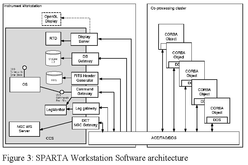
Mathematical processing is required for the tasks of atmospheric statistics estimation, calibration, and loop optimisation.To support these operations, highly optimized parallel mathematical libraries are available.Recording of AO loop data in real-time is required for system calibration and for diagnostic purposes. The volume ofdata produced by a multi-sensor AO system is in the region of 80Mbytes/s. To be able to stream these data to disk inreal-time for periods of more than a few seconds a RAID array is required. One computer of the cluster is equipped witha RAID interface connected to an appropriately sized internal RAID array and perform the task of data recording.In any distributed system the selection of the middleware supporting inter-process communication and data distributionis a key design choice. For a platform designed to be used by VLT 2nd generation instruments clearly a standard VLTSW interface for commands and on-line database is essential; however the usage of the standard VLT SW was notconsidered appropriate for highly multi-threaded systems such as SPARTA. As a result of a joint internal effort, theselected middleware for SPARTA is ACE/TAO with DDS providing a CORBA implementation for method invocationand an implementation of the OMG Data Distribution Service for publish-subscribe data distribution.However SPARTA is still a system intended to run within a VLT SW environment, therefore a number of gateways areprovided. Those gateways are modular components that are added to the system to interface it to the observatory, but arenot strictly part of the platform itself. In fact the SPARTA could run without gateways. Those are:
- CCS Command and Error gateway:
The gateway receives standard CCScommands specifying which object toaddress, the method to invoke and theparameters to use. Then the gatewaytranslates the command to a CORBAcommand, including type conversion forthe parameters, and waits for the reply ofthe object. The object replies with aCORBA sequence that is translated to astring and/or status (OK or FAILURE).In the event of an error, received asCORBA exceptions, the gateway packstogether all the errors generated at thevarious stages of the computation into aCCS ErrorStack and returns it to thecaller. At the same time, the error stack isalso sent to the log system. - Log Gateway:
The gateway subscribes to a dedicated DDS topic and posts to the standard log system all the log messagesgenerated by the SPARTA objects, either simple text messages or FITS logs. - OLDB Gateway:
The gateway subscribes to a dedicated DDS topic. Each packet carries the name of an object and the parameter thathas been changed so that the OLDB Gateway can map this event to a On-line DB point with structure"SPARTA:<object name>.<parameter name>" to which the specified value is assigned. In this wayparameters like state, substate, initialised, error and others are visible from the On-line DB andcan be shown in standard panels. - Display Server:
The Display Server attaches to RTDF sources (DDS high performance topics) to display various dynamicalinformation like the pixels on the detector or the voltages of the mirror through either a standard RTD at low speed(maximum few Hz). - NGC Gateway:
This gateway offers a CORBA interface to drive the NGC workstation process (which is a VLT SW process) fromthe SPARTA CORBA objects. - FITS Header/Table generator:
This component subscribes to specialised DDS topics that collects period information about the system, typicallyperformance figures. Those data are used to populate a FITS table that is initialised at the beginning of theobservation and closed at the end. At the end of the observation this process also generates an AO FITS Header thatadds extra global information on the performance of the AO system during the observation.Those FITS files are then passed to the upper level software components to be merged with the final scientific files.Content of the table and header are system dependent.
All the gateways and VLT SW processes run in the Instrument Workstation.
 |
The SPARTA co-processing cluster implements a number of soft real-time applications which do not require low latencybut do require a significant amount of computing power. These applications include calibration, atmospheric statisticestimation and loop optimization amongst others. One process running in the cluster coordinates the operations of thesoft-realtime applications with those running in the hard-realtime box and provides a single interface to the RTC.The hardware solution selected to implement the SPARTA co-processing cluster is a collection of multi CPU, multi coreLinux computers connected to the SPARTA real-time box by means of a private Gigabit Ethernet.The software running within the SPARTA supervisor is inherently distributed and requires the normal facilities ofdistributed systems: message passing, centralized logging, error reporting, distributed database access. Each applicationis implemented as a separate server derived from a standard SPARTA object class implementing a number of standardCORBA interfaces.The applications running within the cluster can be divided into the following categories:
- Coordination
One computer within thecluster acts as the SPARTAsupervisor. A singleapplication running in thecluster coordinates allapplications running withinthe cluster together with thoserunning in the RTC box.Additional componentsoperating in the clustercoordinate the acquisition,reconstruction and controlcomponents running in theRTC box. - Calibration
A calibration applicationimplements the basicinteraction matrixmeasurement techniquessupported by SPARTA andprovides a mechanism bywhich to invert interactionmatrixes to create and store acontrol matrix. Additionalcalibration techniques can be provided which are specific to each instrument by extending the basic calibration task.Multiple calibration objects can run to serve different loops. - Auxiliary Processing
A number of auxiliary processing applications are required for loop optimization and atmospheric statistics estimation. - Data Recording, Distribution and Measurement
One computer within the cluster is sized appropriately to acquire all of the data from the RTC box in real time. Thiscomputer is equipped with a high throughput RAID array. Applications running on this computer are provided tostream data to the RAID array, distribute data to the instrument workstation for graphical display, and performmeasurements such as averaging of RTC data frames.
 |
To support the development of the various cluster applications a number of support packages are provided, thesepackages are:
- Configuration Data Management System (CDMS)
All adaptive optics systems need to generate and share vectors and matrixes representing control matrixes,background maps etc. To support this functionality a tool is required implementing a distributedpublish/subscribe interface, this tool is known as CDMS. - SPARTA Drivers
To provide a clean interface separation between cluster and RTC box the functions within the RTC box areinvoked by means of a network driver with a simple client server protocol supporting the operations of readingand writing memory and invoking commands. A set of classes implementing a basic SPARTA server and clientinterface is provided. - Mathematical Package
The bulk of the processing performed by the auxiliary processing applications takes the form of FFT, SVD orMVM operations. To support these operations a set of mathematical libraries is included as part of the SPARTAplatform.
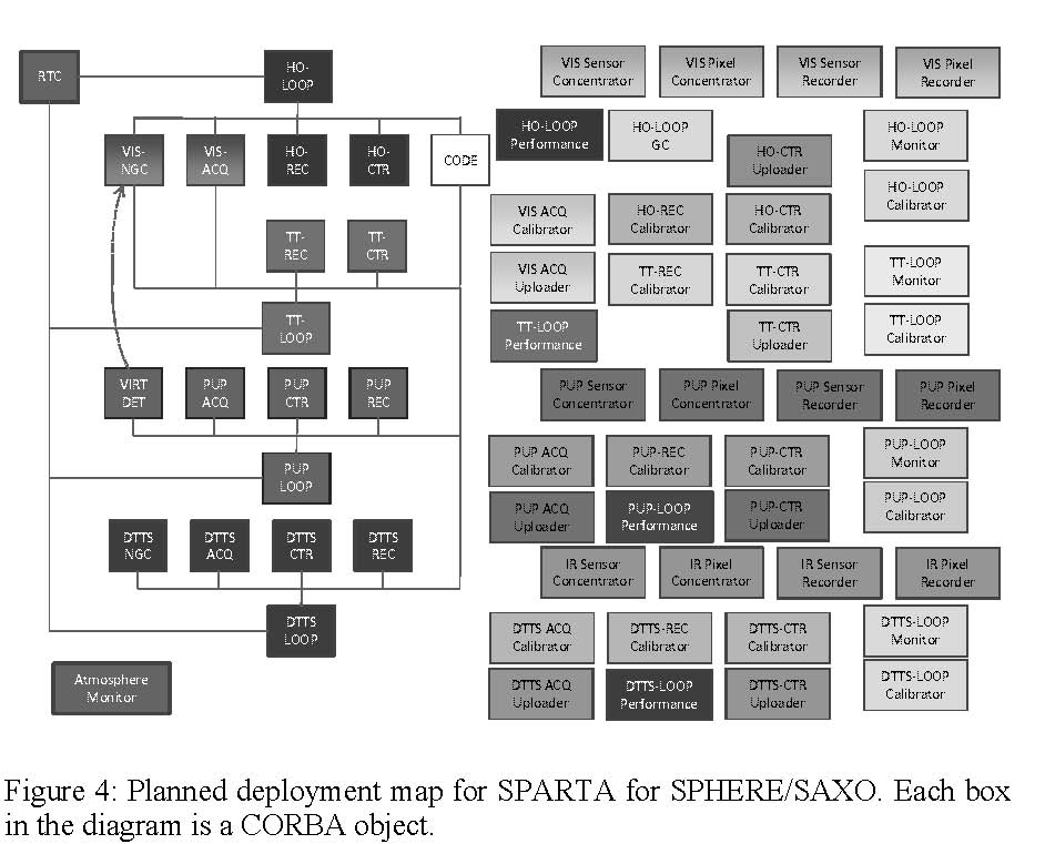
The intended deployment of the SPARTA objects for the SPHERE case is shown in Figure 4. This diagram shows 4different loops: HO for High-Order, TT for Tip/Tilt, PUP for Pupil control, DTTS for Differential TipTilt Sensor (a looprunning with an infrared sensor). Each loop has 5 core objects, a DET (detector interface, also a gateway), ACQ(acquisition), REC (reconstructor) CTR (Controller) and CODE (Corrective Optics Drive Electronics) and a number ofauxiliary tasks to perform other functions like calibration or parameters tracking.
Data Distribution
A key component of the SPARTA architecture is certainly the data distribution. SPARTA uses DDS (Data DistributionService) for 2 purposes: real time high-throughput data distribution and event notification.The former is clearly the most importantapplication. In MACAO and MAD this layerhad been developed using a custom TCP/IPbased protocol. SPARTA added therequirements of multiple clients on differentmachines all receiving the same stream, upto 80 MB/s. Multicast was an obvioussolution to this problem and DDS providedus with a off-the-shelf implementation of amulticast protocol.
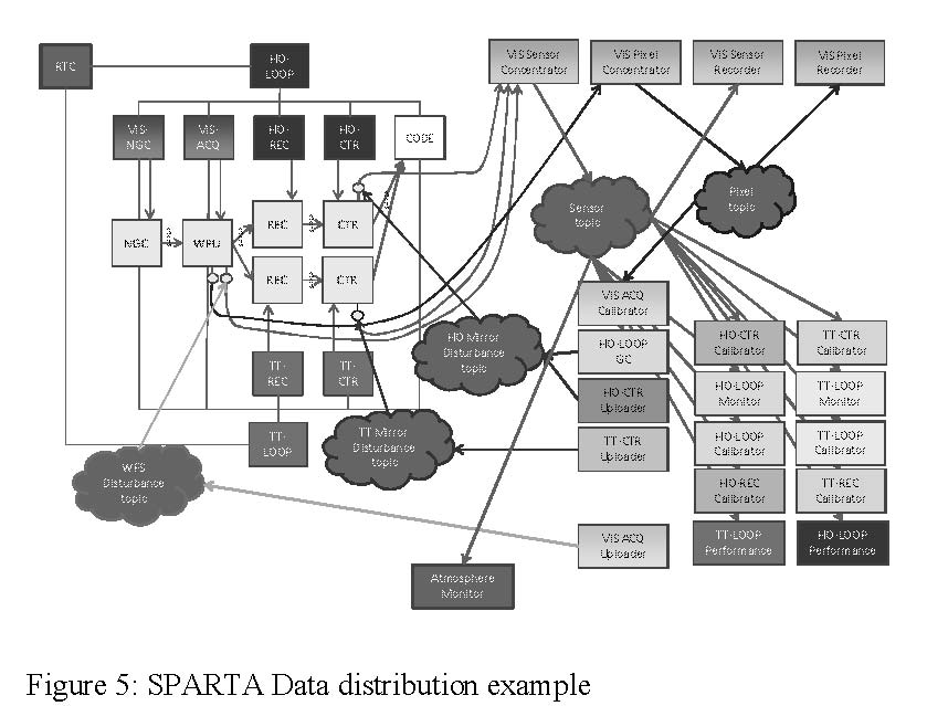 |
Figure 5 shows an example of SPARTA datadistribution. The real-time box modules (inyellow) publish data using the custom pointto-point RTDFL protocol (TCP-based). Dataare collected by a "data concentrator" thatcorrelates packets coming from differentmodules of the real time box but sharing thesame frame counter, builds a "super-packet"and publishes it to the cloud via DDS.Several clients are listening for this packetfor different purposes: calibration,performance estimation, loop optimization, etc. Clients can be added transparently without affecting the rest of thesystem thanks to the multicast implementationDDS is also used in SPARTA to replace the CORBA notification service. This has been done to experiment with the coexistenceof CORBA and DDS and to show that events and logs can easily travel via DDS topics.
SPARTA light
SPARTA-Light is a simplified, scaled-down version of the SPARTA platform targeting smaller complexity systems. Ithas been created to re-use the SPARTA platform as much as possible at a significantly lower cost.
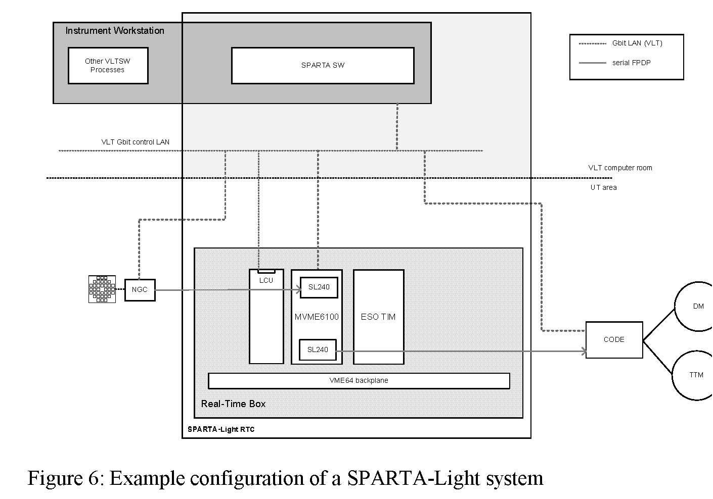 |
The aim of the SPARTA-Lightproject is to provide a standardplatform to build small to mediumcomplexity adaptive optics realtimecomputers. As well asSPARTA, SPARTA-Light is notan AO RTC, but provides theconcept how to build one, areusable infrastructure and a set oftools. As such, the SPARTA-Lightplatform is the combination of theitems below:
- Hardware specificationsdefining the systembuilding blocks
- A software frameworkproviding functionalitycommon to all AOsystems - e.g.communication,configuration, storage, math, etc.
-
Interface definitions:
- External interfaces: connected to sensors, actuators, networks, etc.
- Internal interfaces: interconnecting the different hardware and software components
A SPARTA-Light RTC consists of two main components:
- A real-time SW processing pipeline known as the Real-Time Box
- An Instrument Workstation hosting standard VLT SW as well as SPARTA-specific SW
SPARTA Light Real Time Box
The Real-Time Box handles all tasks directlyinvolved in the AO real-time control. It isbased on a 19" VME system hosting at leastone embedded computing board. The Real-Time Box continuously sends sensor andactuator data to the Instrument Workstationfor further processing using the GigabitEthernet control LAN. All sensors andactuators are connected to the Real-TimeBox via 2,5Gbit/s sFPDP fibre links.
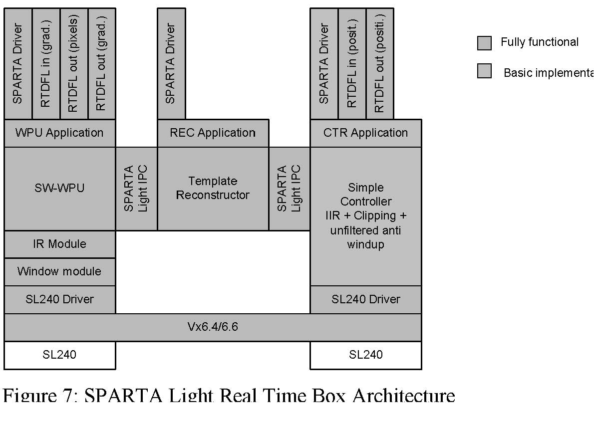 |
The SPARTA-Light reference designintegrates all major AO loop processingblocks in a single real-time processingboard:
- ACQ: Acquisiton and Wavefront Processing Stage, converting pixels to gradients
- REC: Wavefront Reconstruction Stage, projecting gradients to mirror space
- CTR: Actuator Control Stage, performing the control actions
The main SW components in the SPARTA-Light real-time processing board are presented in Figure 7: SPARTA LightReal Time Box Architecture following a hierarchical (i.e. layered) approach. Two main component types must bedistinguished:
- The blocks in green are fully functional as provided by the SPARTA-Light Reference Implementation and donot require further specialization for use by the specific SPARTA-Light system. They share most of the codewith the mother platform.
- The blocks in orange are to be replaced by specific components for each particular SPARTA-Light system. TheSPARTA-Light Reference Implementation provides only a template implementation for them together with thespecification of their API. It is the responsibility of each particular project using the platform to furtherdevelop/re-implement these components.
In the cases considered for SPARTA Light we expect that the reference implementation, which is derived directly fromthe SPARTA mother platform, will suffice for most of the blocks, with the notable exception of the controller. In factSPARTA Light is intended to be used in the VLT Interferometer and therefore must be equipped with piston controlalgorithm as well as more sophisticated saturation management algorithms, which are not developed as part of themother platform. The SPARTA Light IPC deserves a quick note: it is based on the mother platform RTDFL (Real TimeData Flow - Low level), which is a custom protocol resembling DDS. In fact one must define a topic that is sent acrossan RTDFL interface. This protocol is the same used to send the metrology to the supervisor via TCP/IP which is thenfurther redistributed with DDS. The platform provides both a shared memory implementation as well as a TCP/IP one,with identical API. It is therefore easy to relocate one or more blocks on different machines therefore a configurationwith 2 (or even 3) CPU boards can be used with SPARTA Light, where each board can run the ACQ or the REC or theCTR or a combination. Clearly at the expense of a higher latency, due to the communication over TCP/IP over a crossoverEthernet cable.
SPARTA Light Supervisor
The SPARTA-Light platform reference design reuses the SPARTA High-Level SW components and deploys them onthe Instrument Workstation together with the standard VLT SW, therefore using one single machine where the SPARTAmother platform used an Instrument Workstation to host the UI and an array of servers for the supervisor.All the components of the SPARTA platform can be reused in SPARTA Light after customization to the size of thesystem (topic definition). Given the modularity of the supervisor architecture, additional components can be easily addedto fulfill specific functions like piston management or saturation management, which is left to the particular project.
Status and Performance
SPARTA is designed to serve 2nd generation VLT instruments, in particular SPHERE, GALACSI and GRAAL. Inaddition SPARTA Light will serve a low-order system for the Auxiliary Telescopes (NAOMI) and probably GRAVITYas well (TBD). A fourth system serving the third focus of the AOF is under study.
Table 1 lists the systems of the main platform and their main parameters. The total complexity is computed as theproduct of the length of the gradient vector times the number of actuators of the mirrors times the frequency, withouttaking into account the latency.Table 2 lists the portfolio for SPARTA Light, but in this case all the parameters in the table are TBC since thoseinstruments are in early stage of definition/development.
Table 1: SPARTA main platform portfolio
| System | Type | #s | DoF | #m | DoF | FRQ | Latency | Complexity |
| SPHERE | XAO | 1 | 40x40 | 1 | 1320 | 1500 | 150µs | 5 GMAC |
| GRAAL | GLAO | 4 | 40x40 | 1 | 1170 | 1000 | 300µs | 12 GMAC |
| GALACSI | LTAO | 4 | 40x40 | 1 | 1170 | 1000 | 300µs | 12 GMAC |
Table 2: SPARTA Light portfolio
| System | Type | #s | DoF | #m | DoF | FRQ | Latency | Complexity |
| NAOMI | SCAO | 1 | 5x5 | 1 | 20 | 500 | 1ms | 1 |
| GRAVITY | SCAO IR | 1 | 9x9 | 1 | 60 | 700 | 1ms | 5 MMAC |
SPARTA is now in advance state of development. The first implementation, SPHERE, is scheduled to be completed bymid of 2011, but intermediate reduced-features/fully functional releases will be delivered, a first simple one beingalready done.
At the time of writing the major functions of the real time box have been completed and tested and all the criticalcomponents are in place. The real time FPGA+DSP pipeline has been completed and tested and features extremely lowlatency and almost no jitter. At the current stage of development, the SPARTA real time box for SPHERE/SAXOfeatures about 300µs latency, 200 of which are spent in the controller part, which is implemented in a CPU. In fact mostof the time spent there is to transfer data to and from the CPU. The control loop in the SPHERE/SAXO dimensions hasbeen pushed up to 1.8 KHz.
At the cluster level the infrastructure features already all the critical components, from deployment tools, to CDMS,display tools, all base objects, data recorder. All 5 fundamental objects have been developed for 3 loops (HO, TT,DTTS). Auxiliary tasks are in development and in particular the calibration task is approaching completion. Atmosphericestimation and loop optimization are also in an advanced stage of development.In the coming months the SPARTA team will complete all the features of the real-time box and will finalize the designof the co-odination objects shown in Figure 4.
SPARTA Light, instead, has just started. As a sister project it will inherit most of the code base from the SPARTAmother platform. The core of the work on SPARTA Light, which will be performed in the next 24 months, will be theadaptation of the code of the real time box to run on a smaller system purely CPU-based.
Roadmap and future challenges
SPARTA provides a generic decomposition infunctional blocks that can be applied, unchanged, to a variety of different AO systems, ranging from very small singleconjugate AO with less than 100 actuators to much bigger and faster systems. For AO systems under development,SPARTA provides an implementation for all those functional blocks that are mapped to currently available technologies.The E-ELT with its instruments poses new challenges in terms of cost and computational complexity. Simply scaling thecurrent SPARTA implementation to the size of E-ELT AO system would be unnecessary expensive and in some casesnot even feasible. So, even if the general architecture is still valid, some degree of re-implementation and use of newtechnologies will be needed. This paper analyses the new general requirements that the E-ELT and its instruments willpose and introduces promising technology and solutions that could replace the current ones and show how the SPARTAarchitecture could evolve to address those new requirements.
What's new?
Check for the next lunch Talk.
Quick Links
- Home
- Adaptive Optics group expertise and activities
- Adaptive Optics Systems
- Adaptive Optics Technologies
- AO lunch talks
- Other useful links
Special Event: 20 years of Adaptive Optics at ESO
Contact Us