
The Adaptive Secondary Mirror for the VLT
Contents
- The large deformable mirror technology
- MMT-LBT-VLT large deformable mirror concept
- Hexapod
- Thin glass shells for large Deformable mirrors
- System aspects
- DSM Status
- Pictures gallery
The large deformable mirror technology
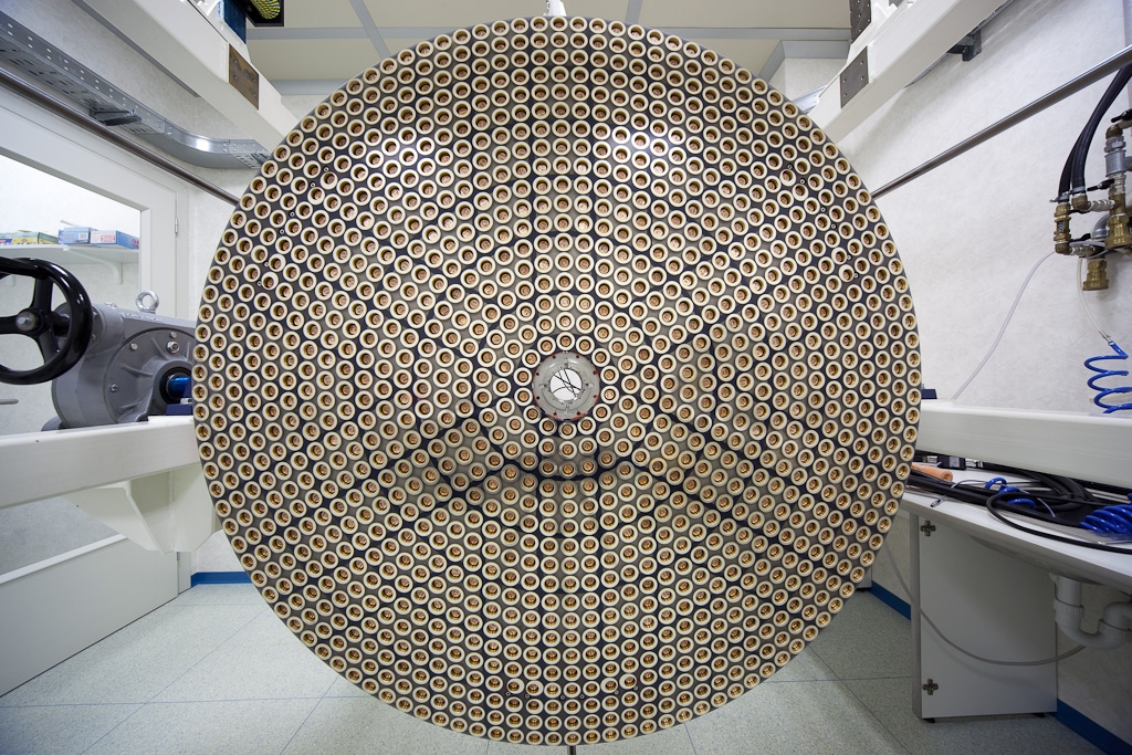
The concept of thin shell and force actuators is one of the most promising in the field of large deformable mirrors; the largest deformable mirror have been built/designed with this technology. A 642mm diameter convex secondary mirror with 336 actuators has been developed and is being used by the MMT (Mt Hopkins, Arizona), while the two 911mm diameter and 672 actuators concave secondary mirrors of the LBT (Mt Graham, Arizona) have being integrated and the first unit has been successfully mounted on the LBT during Spring 2010. The VLT deformable secondary mirror, currently manufactured, is 1120mm in diameter and offers 1170 actuators for adaptive correction.
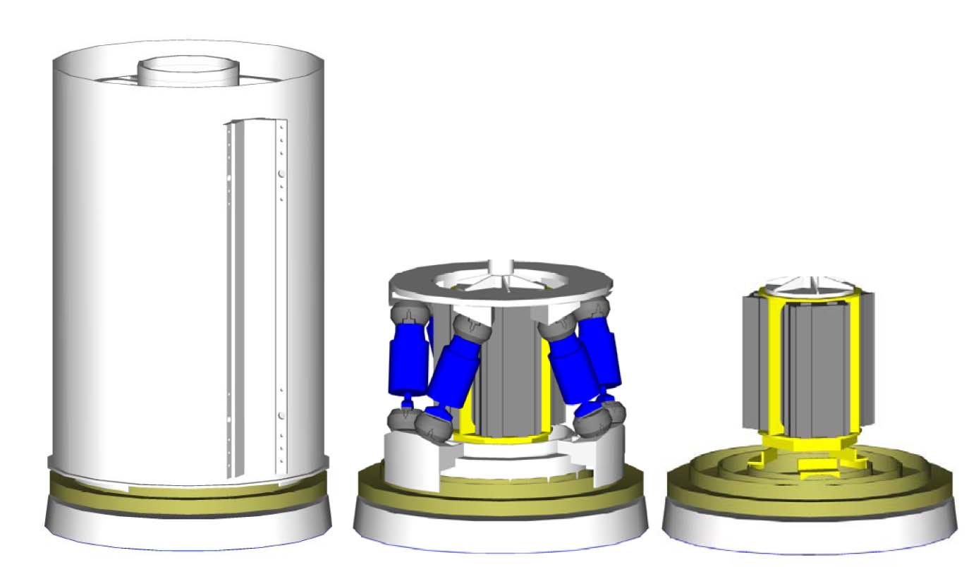
DSM M2 unit assembly: external view (left), hexapod and DSM unit (center), DSM unit (right).
MMT-LBT-VLT large deformable mirror concept
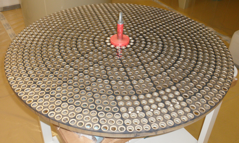
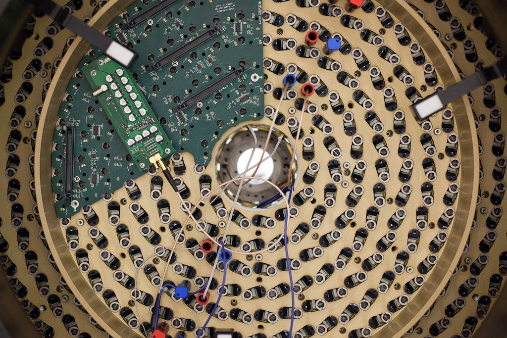
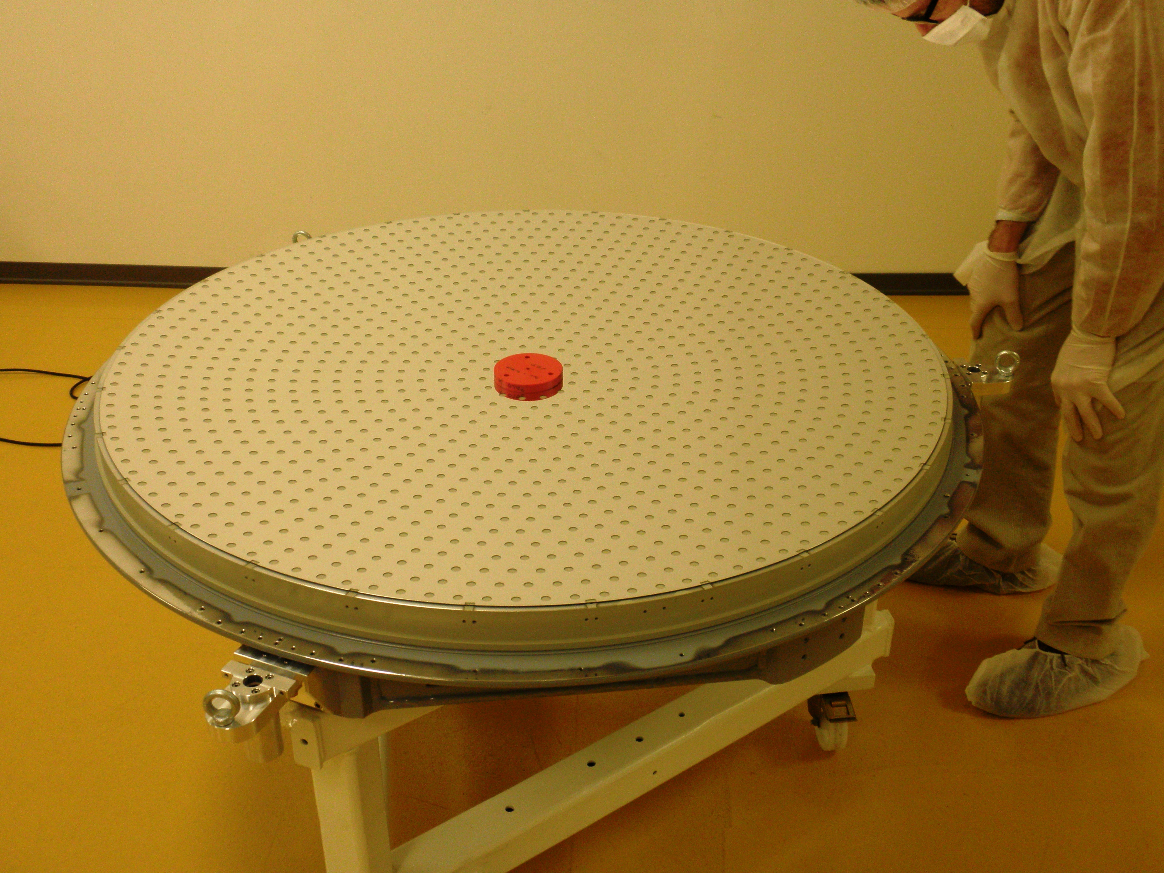
These mirrors are composed of 3 basic elements: a cold plate, holding the voice-coil force actuators, a reference body and the thin shell. Each voice coil applies a force to a corresponding magnet glued onto the back face of the thin shell. A ring of conductive material (chrome, aluminum, gold) is deposited around each magnet and is mirrored on the reference body. These two opposite coatings constitute a capacitance used as space sensor. The reference backplate being a calibrated optical surface, an equal spacing for all capacitive sensors insures a basic (not optimal) optical quality on the shell.
A typical gap of ~90 µm is proposed for the VLT and provides air damping between the shell and the reference body. An internal control loop at 80 kHz insures that the force applied maintains the capacitive sensor to a constant gap. Note also that the derivatives of the capacitive sensor positions provide a measure of the velocity of the shell displacement which in turn is used by the system to define an electronic damping matched to mode stiffness. This feature allows reaching high bandwidth for the system even if some control modes have low resonance frequency.
The cold plate has two functions: holding the voice coil actuators and evacuating heat dissipated by the coils with the help of an integrated cooling fluid circuit.
The reference backplate can be a conventional, thick, ULE or Zerodur optical component, with the exception of the numerous cylindrical openings allowing passage for the actuators. More recent designs (VLT DSM) explored with industrial partner a light-weighting scheme (50-60% light-weighted Zerodur or SiC) to reduce the weight of the complete assembly (realistic without being a huge cost driver). SiC offer the added advantage of being extremely rigid compared to ULE or Zerodur. Note that the front surface of the reference body can be "rough"; the requirement is not strictly speaking the one of an optical surface. Image quality can be specified from the largest linear scale down to a fraction of the inter-actuator spacing. Lightweighted zerodur has been finally selected for the DSM reference body.
Hexapod
A Hexapod is used to produce fine motions on the back-plate; hexapods are particularly well suited for this type of applications allowing fine accurate repeatable motions and high rigidity. Any motion applied to the back-plate is passed on to the optical surface of the thin shell. It can be typically used for small focusing motion and centering correction. It allows as well switching between the focal positions correponding to telescope Nasmyth and Cassegrain telescope foci.
The hexapod is made of six linear actuators. Each actuator is made by a roller screw controlled via a direct drive approach to minimize the backlash. Each actuator is connected by two flexure end joints to avoid non linear effects.
Thin glass shells for large Deformable mirrors
The thin shell remains a high-technology, costly, high risk venture. Up to mid 2009 only the Steward Observatory Mirror Lab has been producing successfully thin shells from Zerodur blanks. In January 2012, SAGEM successfully finished the first thin for the DSM. More information can be found on the ESO announcement webpage and in section Thin Shell status
System aspects
Actuators and magnets
Actual technology imposes magnet sizes of the order of 12mm in diameter and this is what drives the minimum inter-actuator spacing to ~28mm. Reducing this size further brings also complications at the level of the voice coil, but also would reduce the actuator stroke (force). Each actuator is made of a fixed coil and a moving magnet, the latter being glued on the back of the shell. Each coil is mounted on an aluminum could finger that provides the structure of the actuator itself and the path to remove the heat dissipated by the coil. Beside the controlled force, each actuator provides a passive bias force pulling the magnet to hold the shell against the reference plate even when the system is switched off.
The actuators finger are mounted on the cold plate which embed a liquid cooling system to remove the power dissipated at the coil level. The capacitive sensors are co-located at each actuator to measure the gap between the backplate and the shell.
Power dissipation
The VLT DSM will dissipate under median seeing 1326W, 218W for the actuators, 1082W for the crates and 26W in the cables. 4.5 liter/min are needed to dissipate such power and stay within 5 degree temperature difference between the inlet and outlet cooling fluid.
| Parameter | Value |
| Median seeing @30 deg r0(0.5 µm) | 12.1 cm |
| Specifiedfitting error | 78 nm rms |
| Fittingerror (all modes) 1170 |
62.5 nmrms |
| Zernikemodes fitting error | 70.0 nm rms |
| 1170 KLmodes fitting error | 60.2 nm rms |
| max PtVactuator displacement | 13.6 µm |
| max rmsactuator displacement | 1.66 µm |
| max peakforce | 0.82 N |
| max rmsactuator force | 0.17 N rms |
| rms force | 0.157 N rms |
Table 1: Summary ofthe simulation results in the median seeing case. Results of fitting 10000uncorrelated wave-fronts.
DSM status
The system has been completed tested and characterized electo-mechanically. Microgate and ADS delivered the system to ESO Garching early December 2012.
The first Technical Acceptance has been successfully passed during December 2012. The system was mounted on the optical test bench ASSIST in January 2013 and its final optical characterization was successfylly done along spring and summer 2013. The Technical Acceptance 2 was passed in November 2014.
From end 2013 till end 2014, the DSM was extensively tested with GRAAL, first in MCM mode and then in GLAO mode. Early 2015 the GALACSI tests have stated and will be completed by end 2015. The second shell will then be calibreated before shipping the DSM to Chile early 2016.
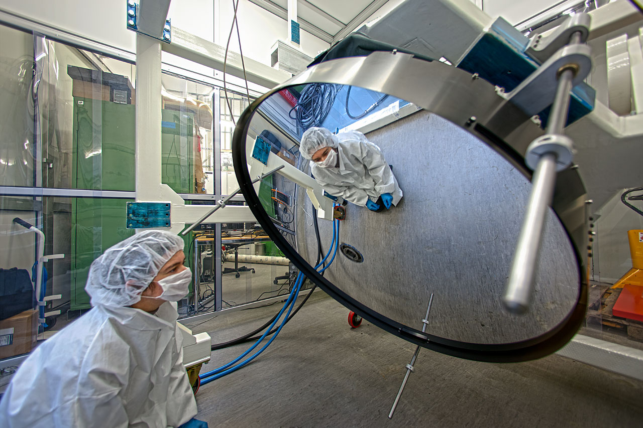 |
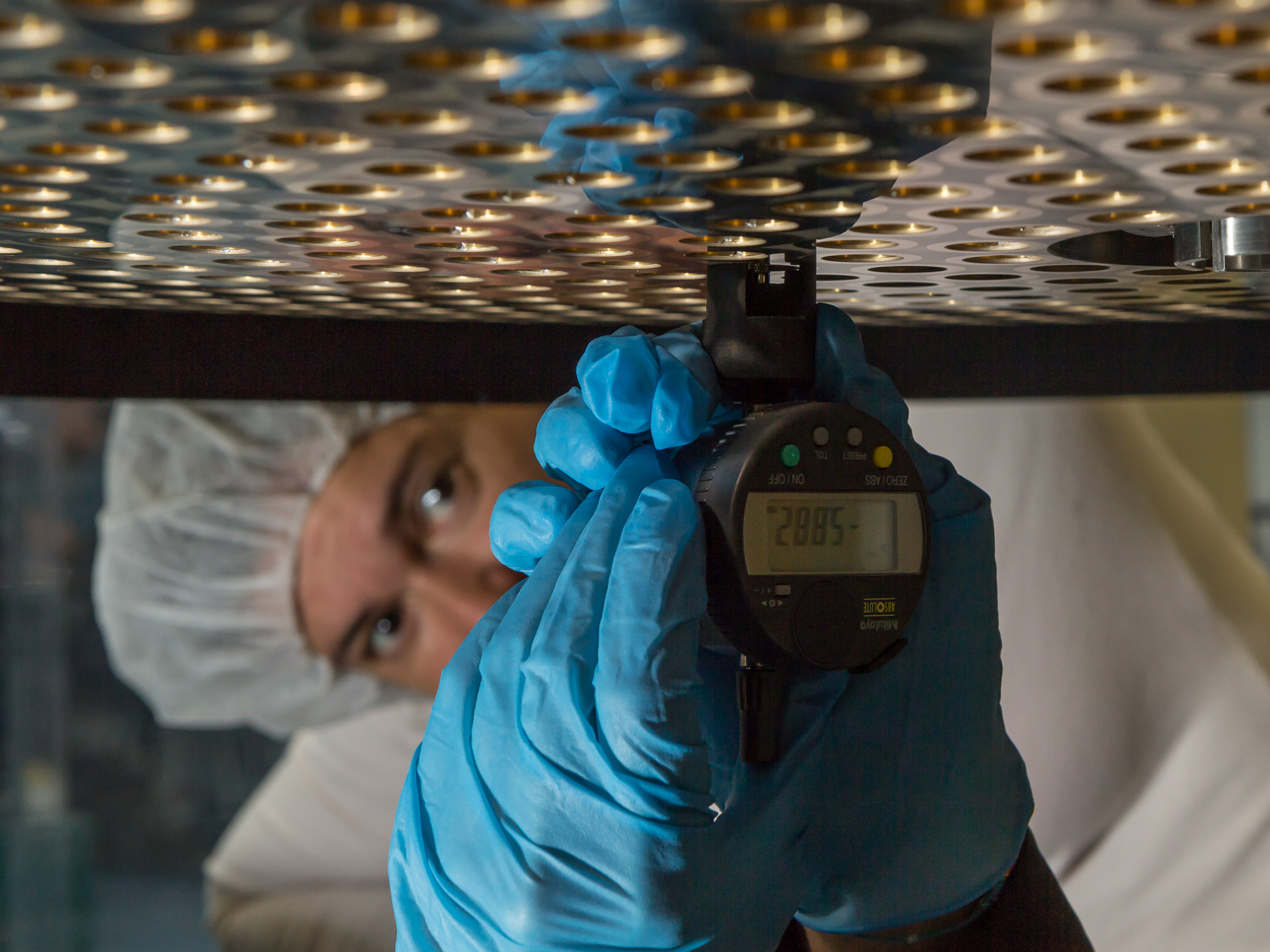 |
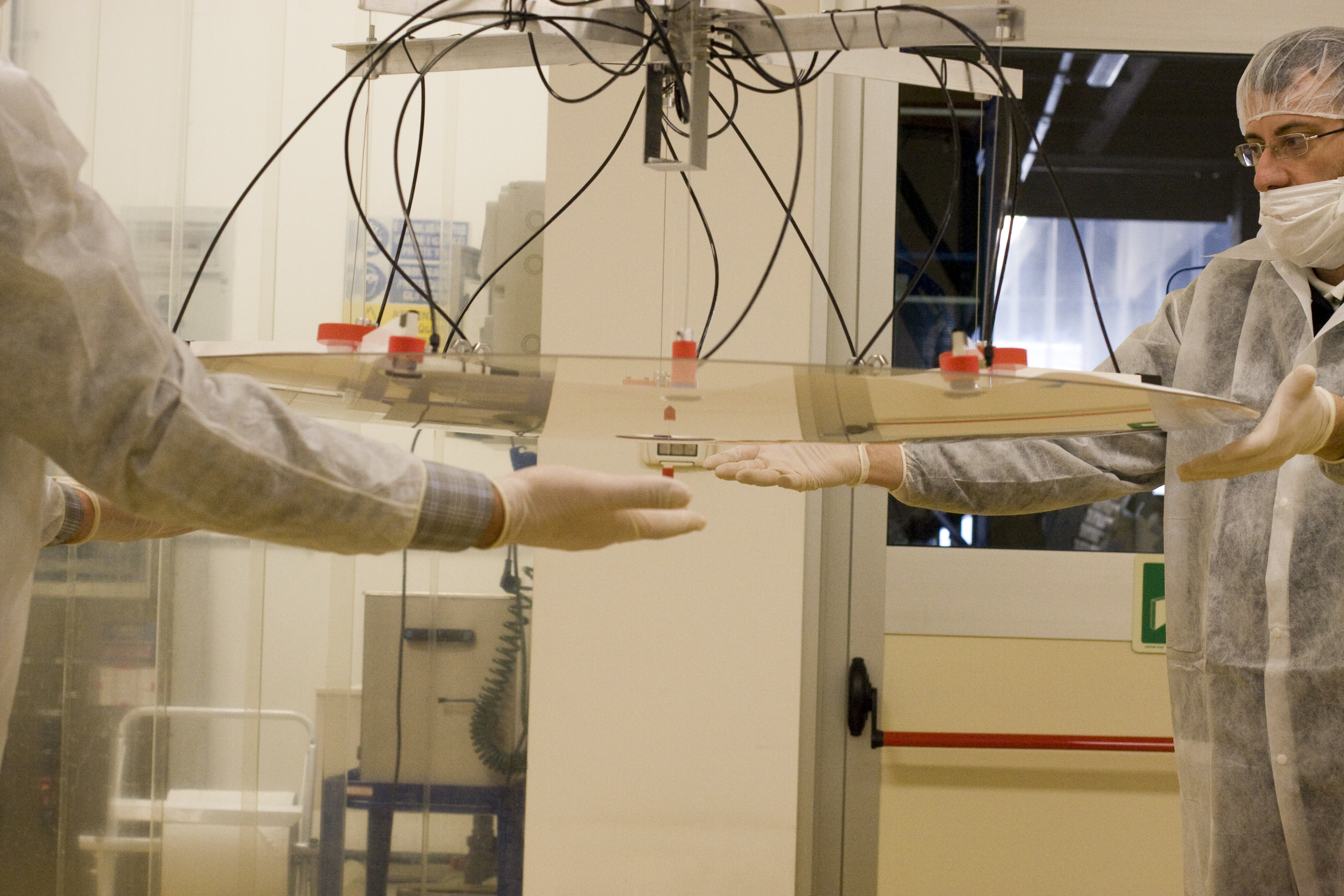
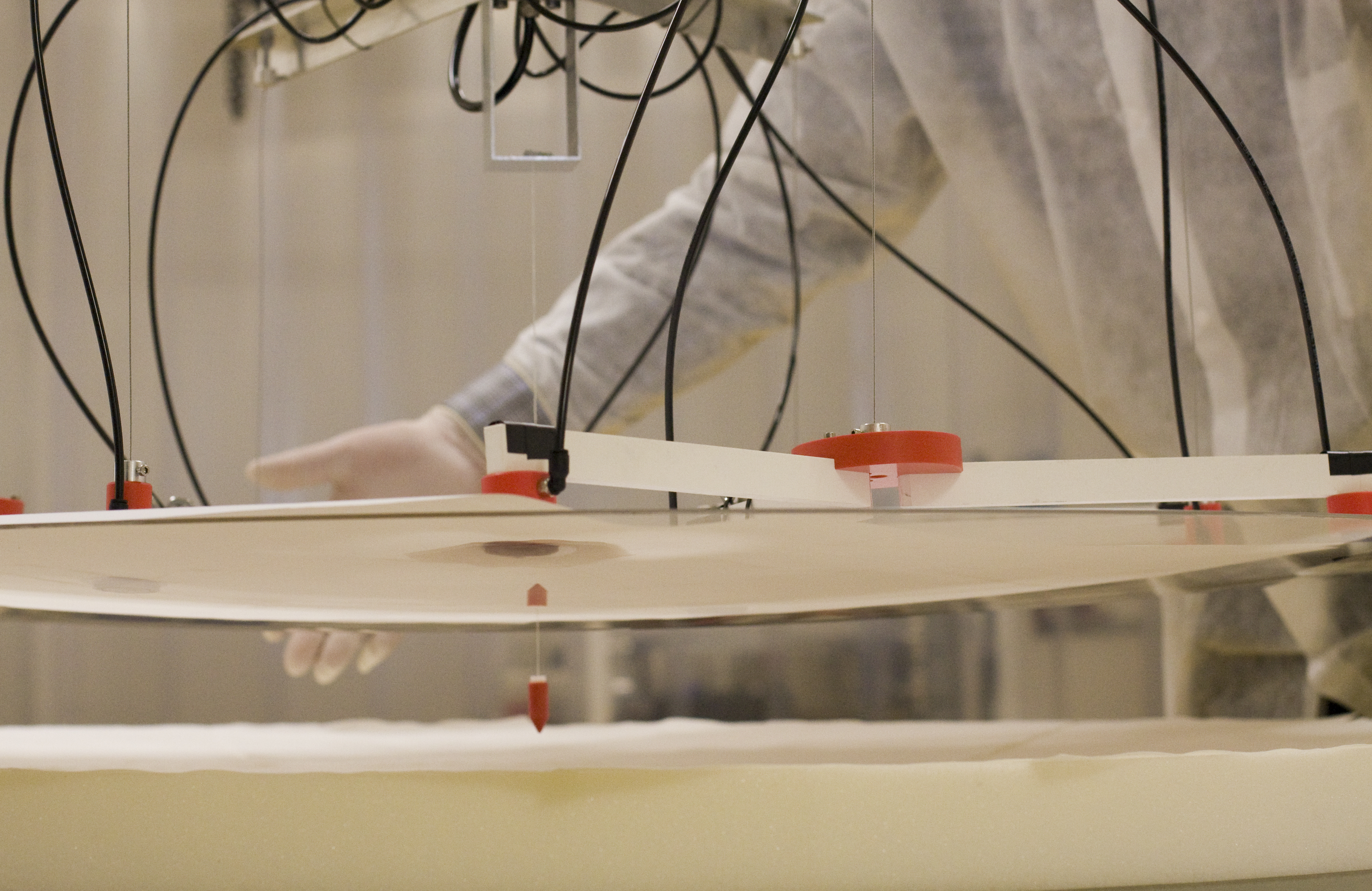
| Super-thin Mirror Under Test at ESO | Measuring the position of one actuator |
More information including pictures is available on Microgate page and ADS international page
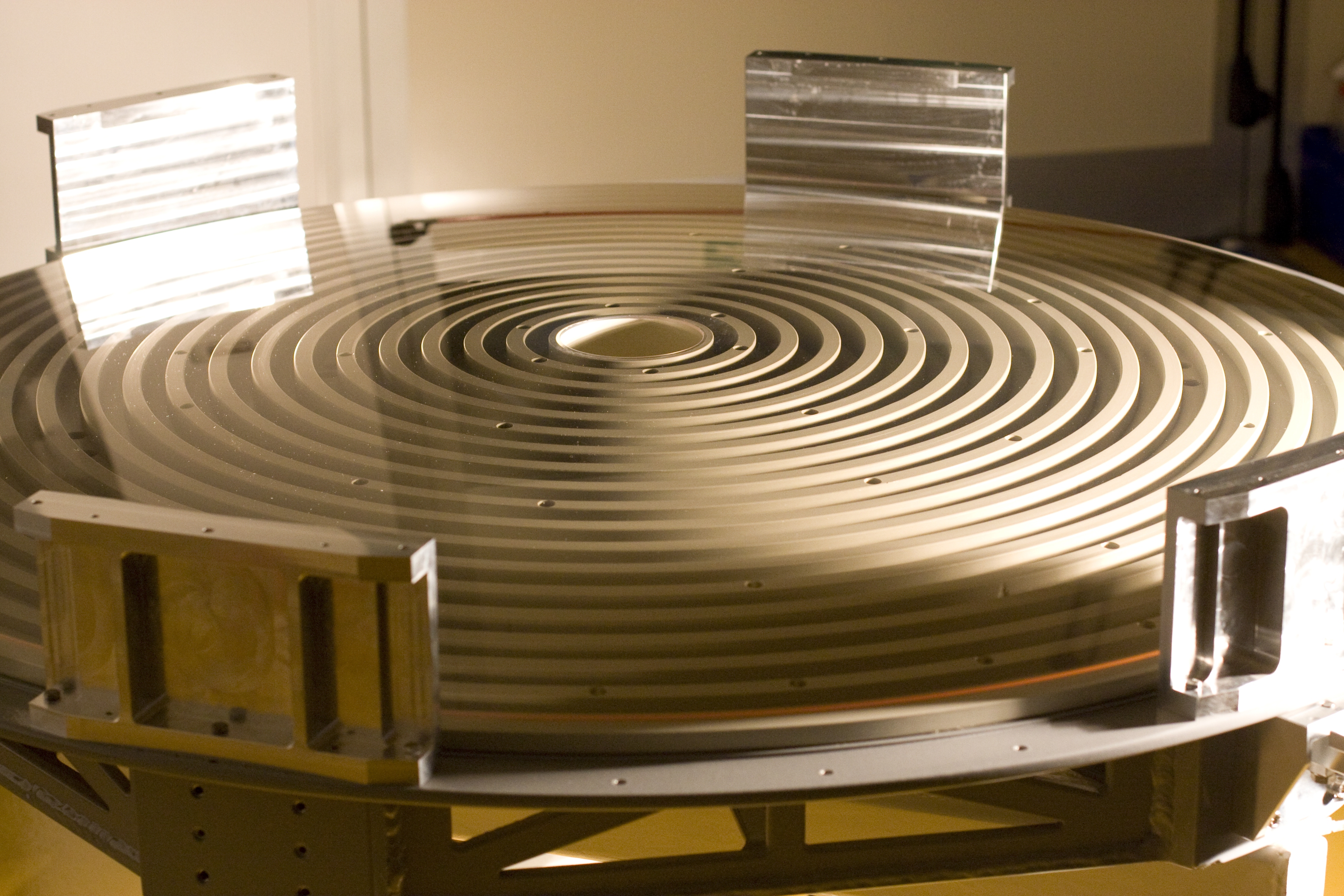
Reference Body
This key Zerodur element was successfully manufactured by SESO mid of 2010. The component has been successfully coated Early February 2011 by ADS International.
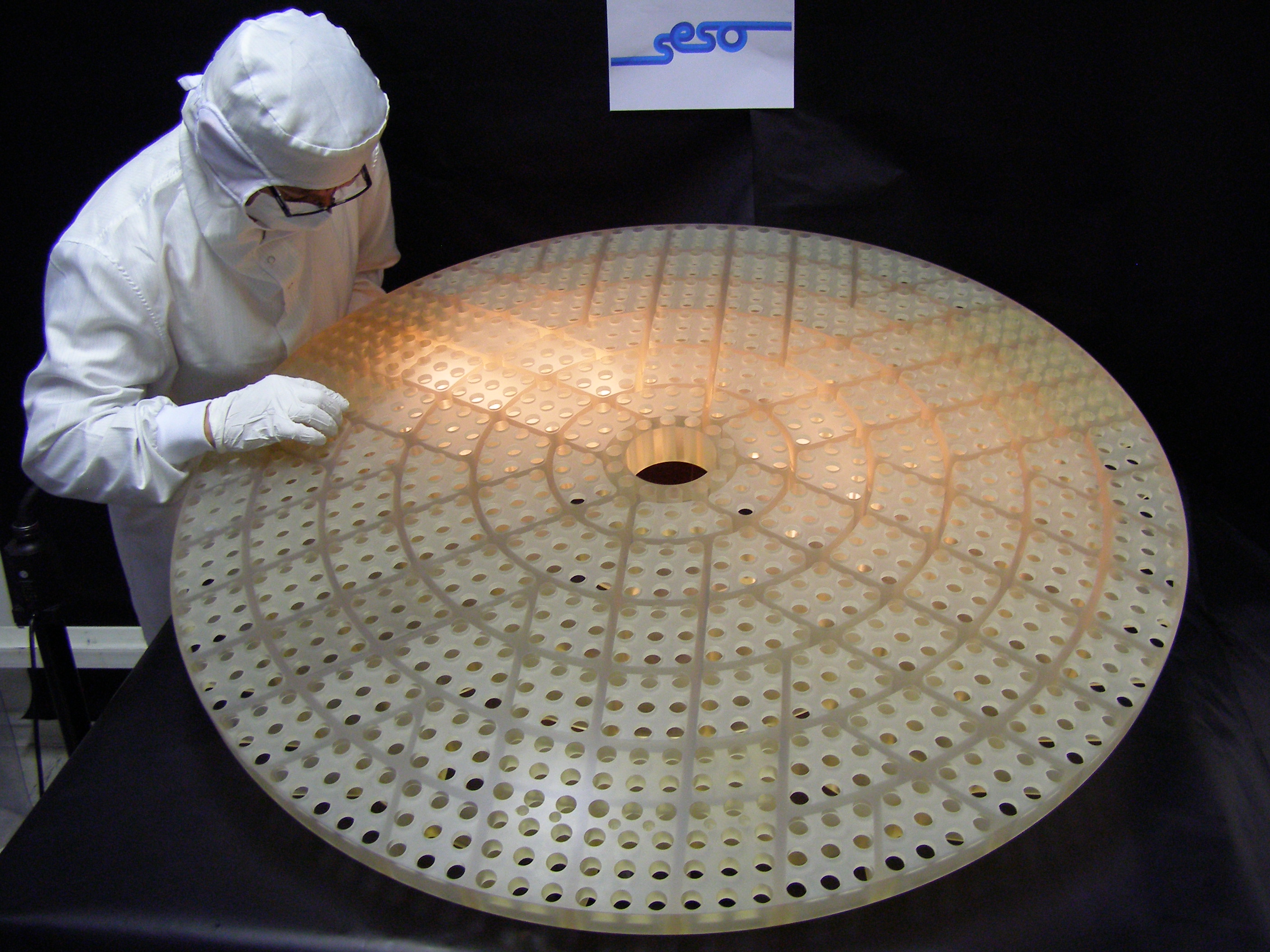 |
 |
| Before coating | After coating |
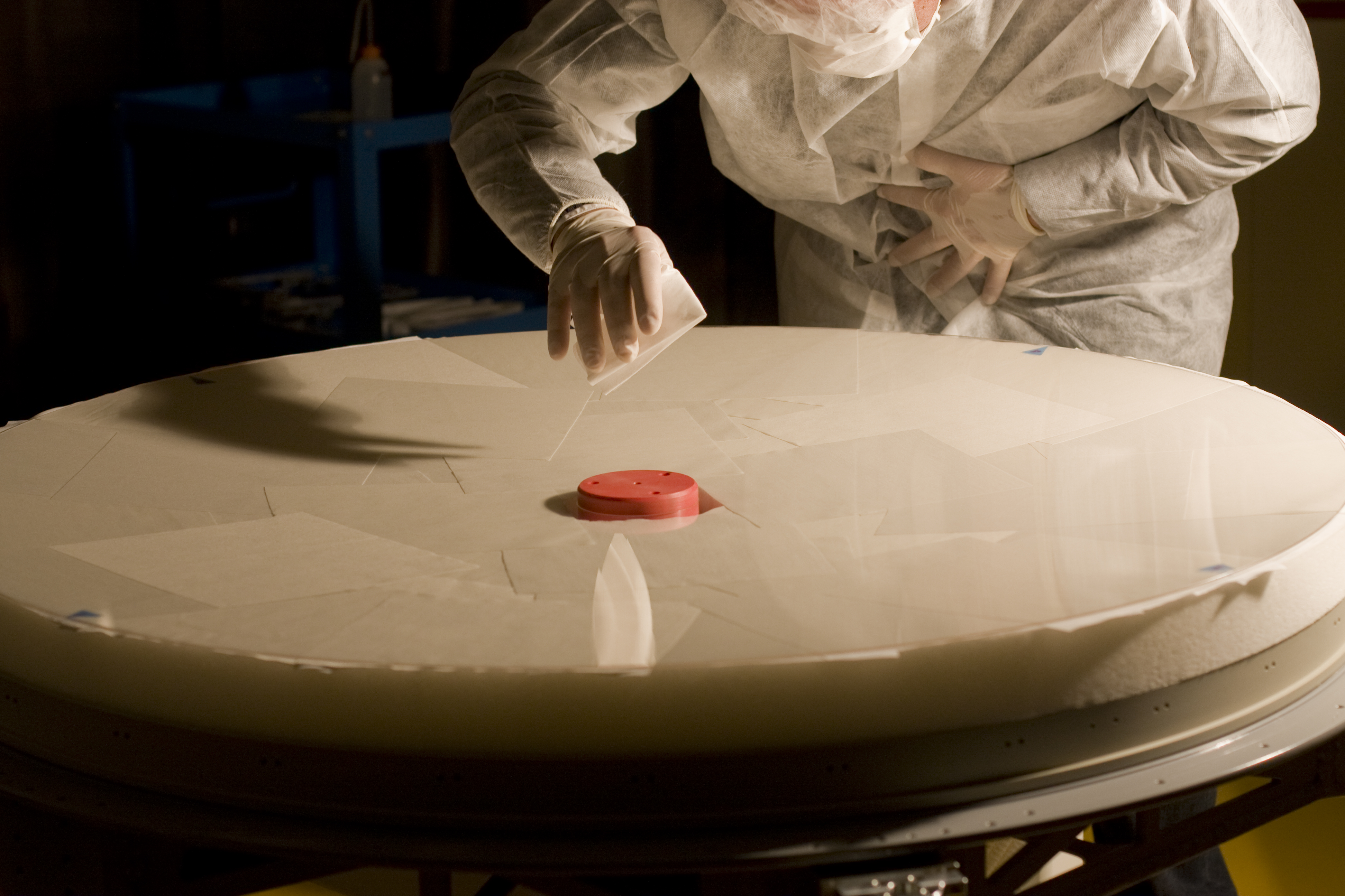
Thin Shell
The thin shell was successfulyl delivered by SAGEM early January 2012. After a detailed inspection and careful cleaning the shell was prepared for the coating of the back surface. ADS has glued the 1170 magnets on the back of the shell and coated the front face. The shell has been electromechanically tested during third and fourth quarter 2012.
Pictures gallery
In this section with present pictures accompanying the progress of the DSM development.
 |
 |
 |
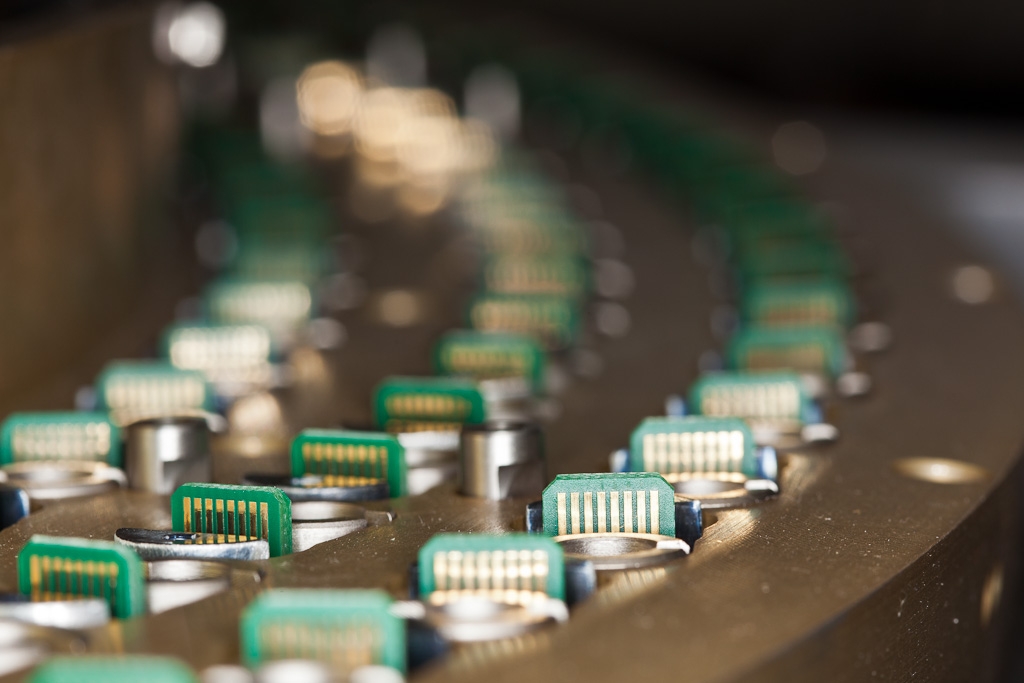
| Actuators | Cold fingers | External ring of actuators mounted on the DSM |
 |
 |
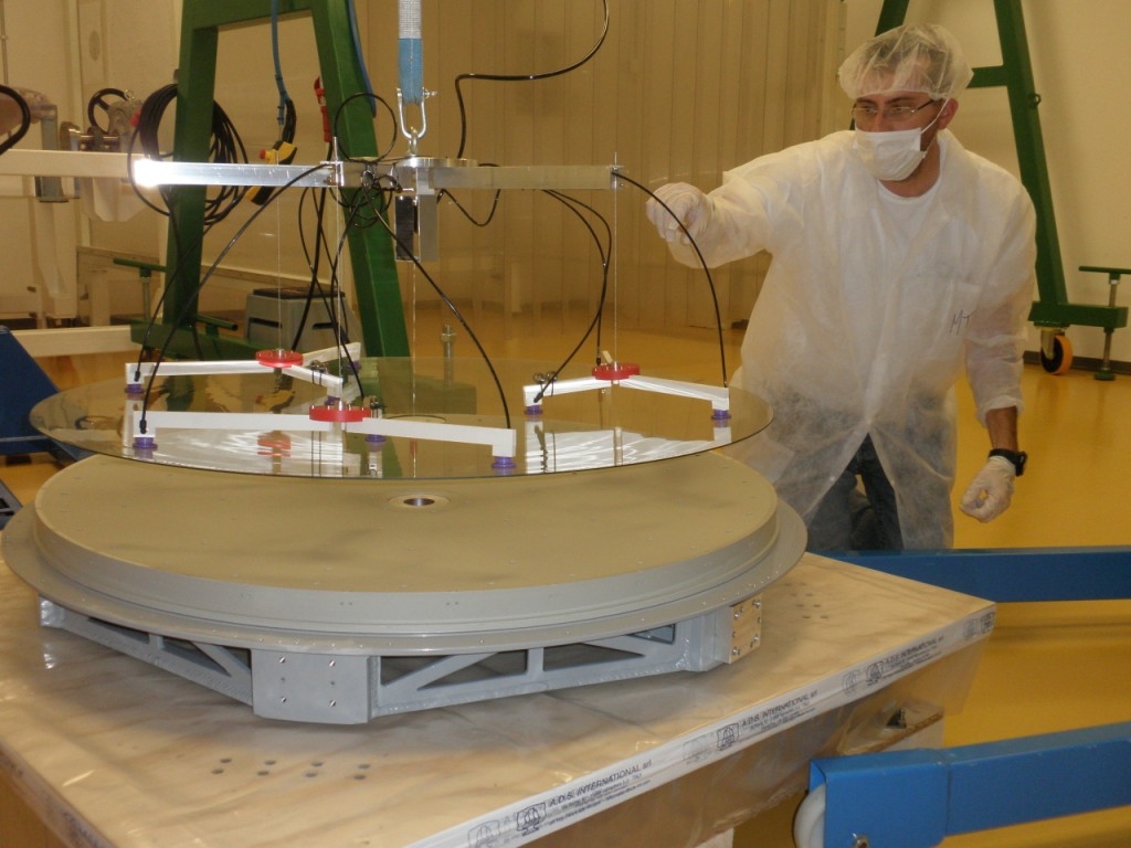 |
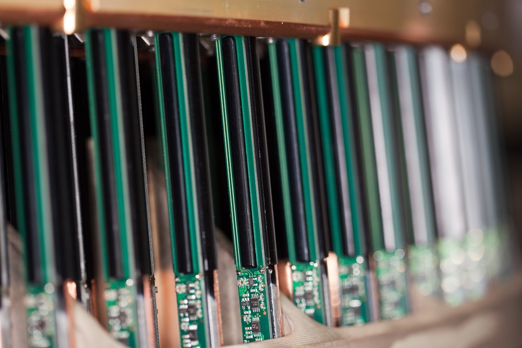
| All the actuators are mounted | First distributions boards | Testing the lifting tool with the slumped shell |
 |
 |
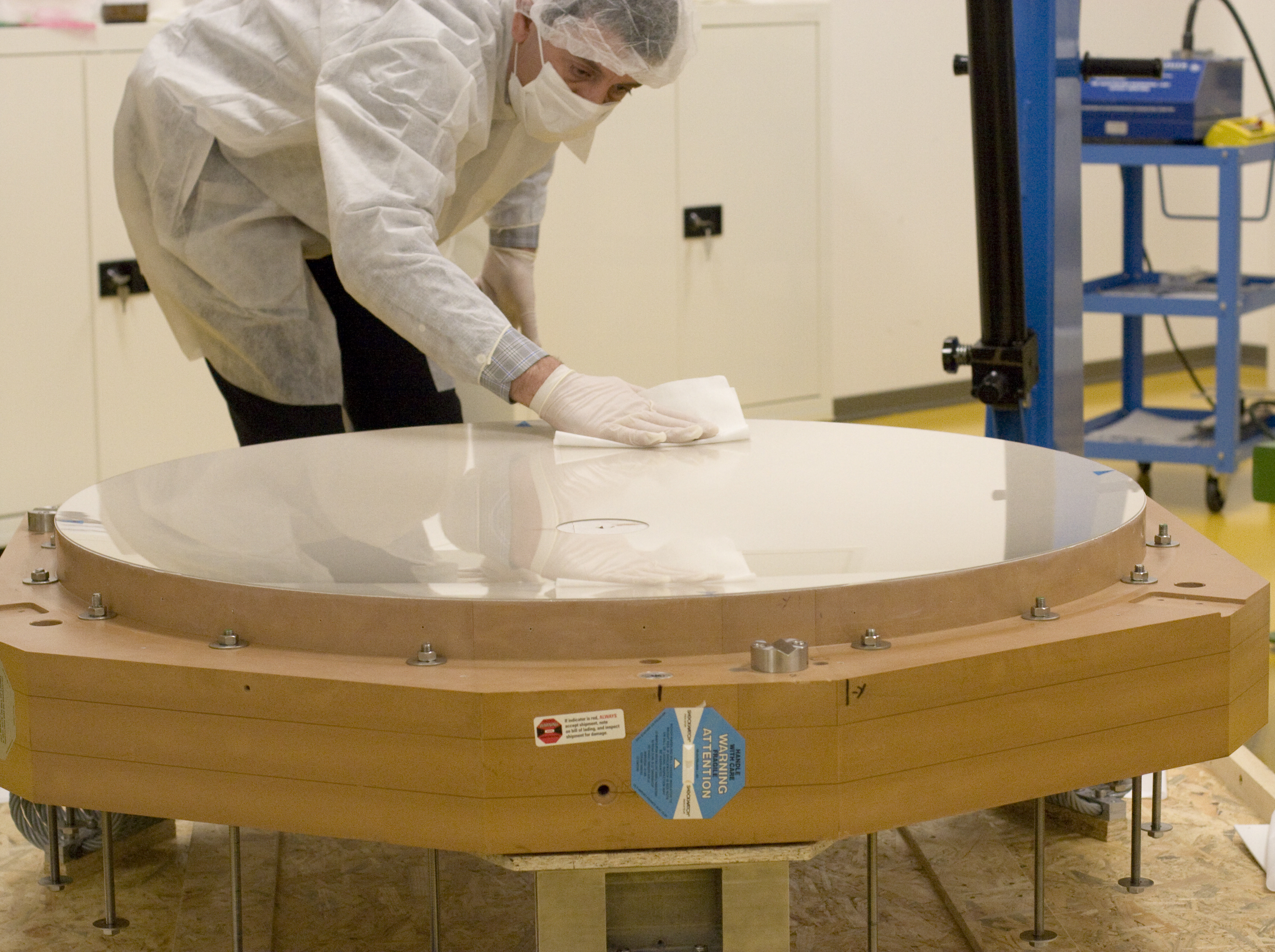 |
| Thin shell lifted by wiffle tree | Changing box | Shell Cleaning |
 |
 |
 |
| Thin shell inspection | Front face | Shell with back coating |
What's new?
Check for the next lunch Talk.
Quick Links
- Home
- Adaptive Optics group expertise and activities
- Adaptive Optics Systems
- Adaptive Optics Technologies
- AO lunch talks
- Other useful links
Special Event: 20 years of Adaptive Optics at ESO
Contact Us