IRACE Interfaces

CLDC CLOCK INTERFACE

Providing Detector Clocks:

There are 16 clocks on each CLDC. Voltage levels are between plus and minus 10 volts, continuous current per channel is 20mA, peak current with 10% duty cycle and maximum duration of 100*s 80mA. Clock rise nad fall times are 50ns.


CLDC DC BIAS INTERFACE

Providing Detector Clocks:

There are 16 DC voltage on each CLDC. Voltage levels are between plus and minus 10 volts, continuous current per channel is 20mA, peak current with 10% duty cycle and maximum duration of 100ms 80mA.
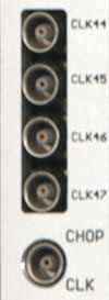
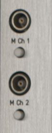

CLDC LEMO INTERFACE

Monitoring of output Clocks:

MCh1: Output of the first channel monitor.

Push the white button to change to the next channel.

The selected channel number is shown by the green color led in binary format.


MCh2: Output of the second channel monitor.

Push the white button to change to the next channel.

The selected channel number is shown by the yellow color led in binary format.


CLDC LED INTERFACE

GIGA-HP RS232 INTERFACE

Providing standard RS232 port interface (11500 bps)

The interface between workstation and IRACE system to send and receive commands.


This interface is used only by the PCI-Ultrasparc based IRACE systems, which is replace by giga-pci card.
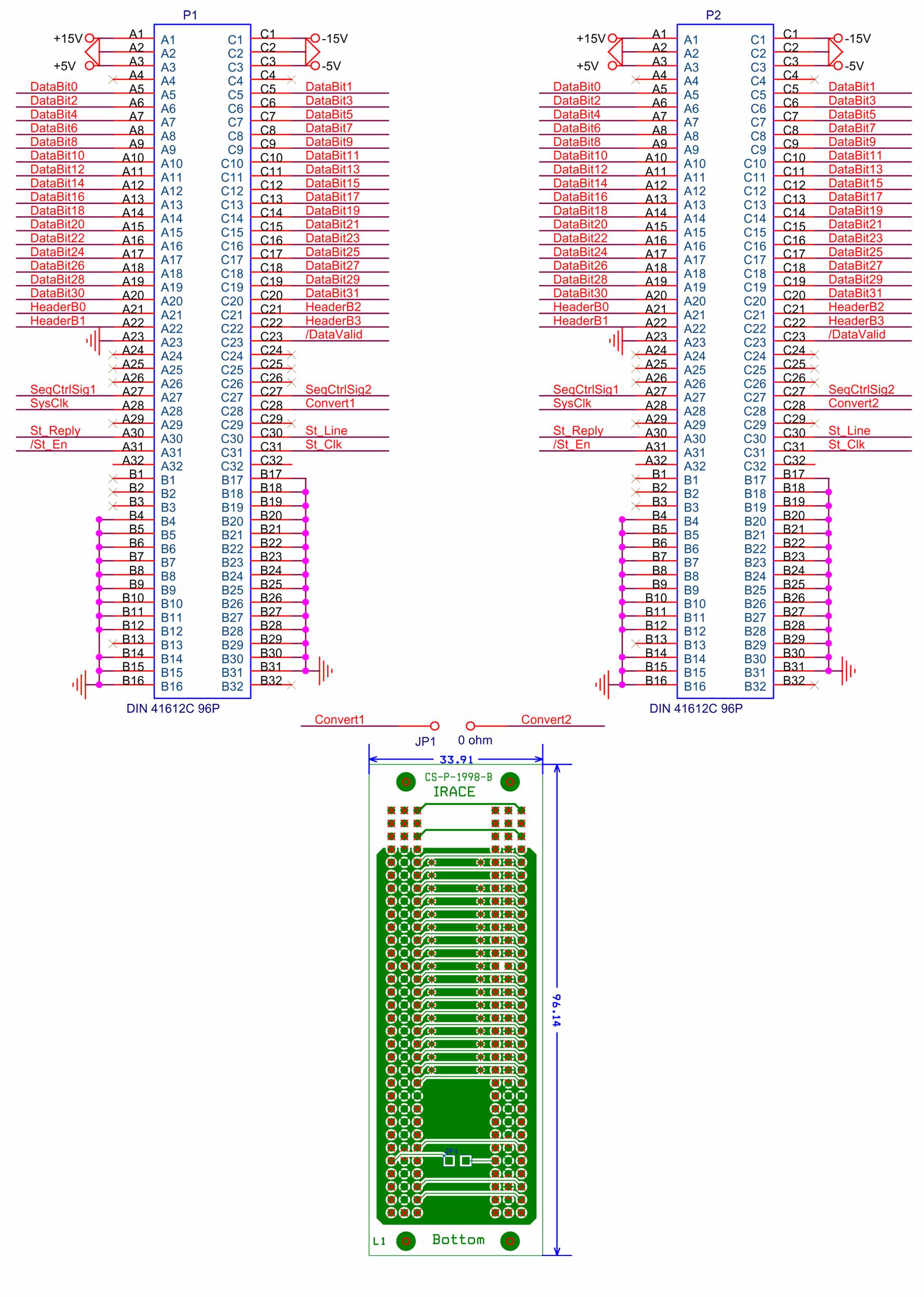

GIGA-HP P2-BACKPLANE INTERFACE

Providing 32 bis data bus

The interface between AQ boards and Giga board.


The "SysClk" is 20 MHz. That mean a data rate of 80 MB/s can be reached.

Pins A30, A31, C30, C31 are for the additional control bus (Status bus), which can be used to setup the not cpu- powered modules like AQ boards.

Four SlotId bits (3..0) are for the address number of each AQ modules.


VME_Bridge connector

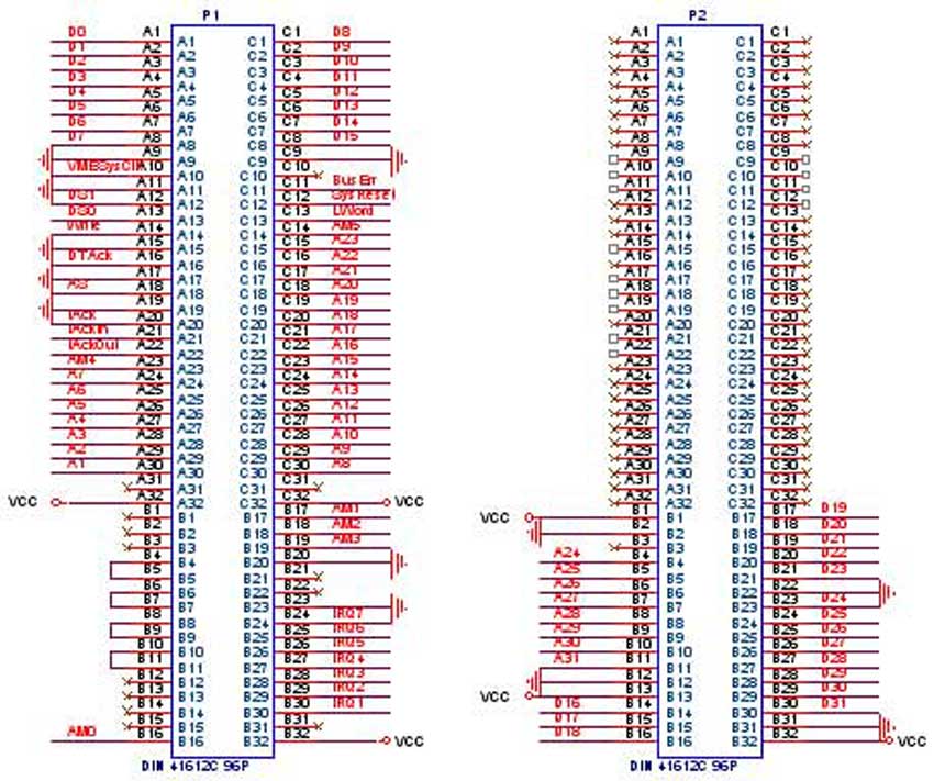
Providing interface between Data interface and Giga module based on VME bus

Those two slotes connect the user I/O pin of vme bus together, column A and C of P2 connector.


Fiber optic cable

Fiber optic cable

Up to 2 Km fiber cable for the interface between frond-end electronics and back-end.


VME64 bus

VME64 is a mechanical and electrical 'superset' of the original IEEE 1014-1987 standard. It offers new features such as

Larger, 64-bit data path for 6U boards.
Larger, 64-bit addressing range for 6U boards.
32-bit data and 40-bit addressing modes for 3U boards.
Twice the bandwidth (up to 80 Mbytes/sec).
Cycle retry capability.
Bus LOCK cycles.


GIGA-HP PARALLEL PORT INTERFACE

Providing standard parallel port interface (BPP mode)

The interface between workstation and IRACE system to send and receive commands.


This interface is used only by the SBUS-Ultrasparc based IRACE systems.


GIGA-HP FIBER OPTIC TRANSCEIVER

SIEMENS V23826-K15-C53/C353

Compact integrated transceiver unit with:
- MQW laser diode transmitter
- InGaAs PIN photodiode receiver
- Duplex SC receptacle
- Single power supply (5 V or 3.3 V)
- For distances of up to 10 km on single mode fiber, and up
to 550 m on multimode fiber (use offset jumper as specified in IEEE 802.3)
This transceiver operates at 1.0625 and 1.3 Gbits per second


GIGA-HP LED INTERFACE

BACKPLANE TRANSPUTER NETWORK (LINKS)

AQ-16CH VIDEO INPUT INTERFACE

Video input interface

Sixteen differential viedeo input interface.

+/- "Ux" are the power supply for the detector board.

+5V was an option for the digital power supply, which is never used.

CtrlSignal is an option for the identification of detector board, but it does not used.


AQ-16CH LEMO INTERFACE

Monitoring of input signals:

Signal plus +.

Signal minus -

Differential signal of both signal plus and minus.


Push button to change to the next channel.


Convert signal


AQ-16CH LED INTERFACE

SEQUENCER CHOPPER INPUT INTERFACE

The chopper control input of sequencer:

The chopper control inputs are on the sequencer front panel auxiliary connector. Two inputs are provided, one for the positive chopper phase and the other for the negative. The lines are named Trigger 1 Kathode and Trigger 1 Anode and Trigger 2 Kathode and Trigger 2 Anode four opto de-coupled lines for TTL level drive signals with minimum pulse width of 2 us (The inputs are at the diodes of an optocoupler with a 1K resistor in series).


SEQUENCER-CLDC INTERFACE

The interface between sequencer and Cldc board. 16 digital signals are connected over the backplane to each Cldc board.

1- Pins A2 to A9 and C2 to C2 are the input interface for Cldc number one.

2- Pins A10 to A17 and C10 to C17 are the input interface for Cldc number two.

3- Two convert pulses (A18, C18) go to tow AQ modules group.

4- Two optinal signals (A20, C20) are only for the future implementation connected to AQ modules, which are currently not used.


SEQUENCER-AQ INTERFACE

Sequencer convert pulse:

The convert pulse comes from Sequencer, which starts the data convertion by each ADC.


SEQUENCER-AQ INTERFACE

Monitoring of sequencer pattern:

Clk44: Pattern number 44.

Clk45: Pattern number 45.

Clk46: Pattern number 46.

Clk47: Pattern number 47.

Monitoring of chopper input signal.


SEQUENCER LED INTERFACE


AQ-4CH VIDEO INPUT INTERFACE

Video input interface

Four differential viedeo input interface.

+/- "Ux" are the power supply for the detector board.

+5V was an option for the digital power supply, which is never used.

CtrlSignal is an option for the identification of detector board, but it does not used.


AQ-4CH LEMO INTERFACE

Monitoring of video input signals:

Signal plus +.

Signal minus -

Differential signal of both signal plus and minus.


Push button to change to the next channel.


Convert signal


AQ-4CH LED INTERFACE