
VIMOS MOS
To use the VIMOS Multi Object Spectroscopy mode users needs to prepare masks with the VIMOS Mask Preparation Software (VMMPS) that can be downloaded from here.
Observing restrinctions
There are several restrictions for MOS observations. The normal mode of observation has historically been with slits oriented N-S and restricting the HA to be within 2hrs from the meridian. We have also required that a pre-imaging run be requested for all MOS observations as masks have been designed based solely on pre-image frames. Now both of these restrictions have been somewhat relaxed, although not in combination. We now allow slits oriented E-W if target declination lies between -45 and -5 degrees. The HA for these observations have been relaxed to be within 3h from meridina. See the short report by Sanchez-Janssen et al. We have also offered a new pre-image-less MOS, PILMOS, mode which does not requires pre-imaging for the observations. See details in the user manual. This mode is offered only for N-S slit orientation.
Grisms
Six grisms are available in MOS mode. The grisms are the same as used in IFU mode, but spectral resolution and wavelength coverage are different. The spectral coverage derived from the automatic reduction of spectrophotometric standard star observationswith VIMOS pipeline is listed in the following table:
| Grism | Order sorting filter | Wavelength coverage | Spectral resolution (1" slit) |
Dispersion (Å/pix) |
Multiplex |
| LR blue | OS blue | 370-670 nm | 180 | 5.3 | 4 |
| LR red | OS red | 550-950 nm | 210 | 7.3 | 4 |
| MR | GG475 | 480-1000 nm | 580 | 2.5 | 1 |
| MR | OS red | 550-970 nm | 580 | 2.5 | 1 |
| HR blue (NEW) | Free | 370 - 535 nm (1) | 1150 @ 402 nm | 0.71 | 1 |
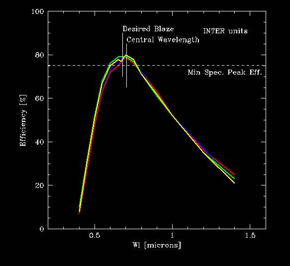
| HR orange | GG435 | 515-760 nm (2) | 2150 | 0.6 | 1 |
| HR red | GG475 | 650-875 nm (3) | 2500 | 0.6 | 1 |
(1) For location in quadrant center. Depending on location, the spectral range can be up to ~370-620 nm
(2) With HR orange grims the spectral range in quadrant 1 (for a standard star) is 505-745 nm
(3) With HR red grisms the spectral range in quadrant 1 (for a standard star) is 650-865 nm
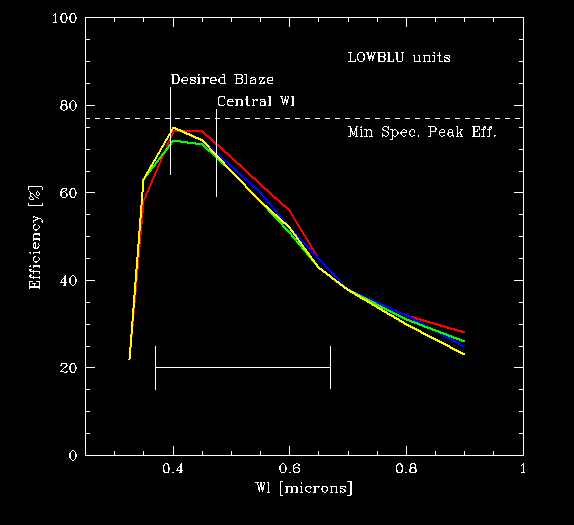
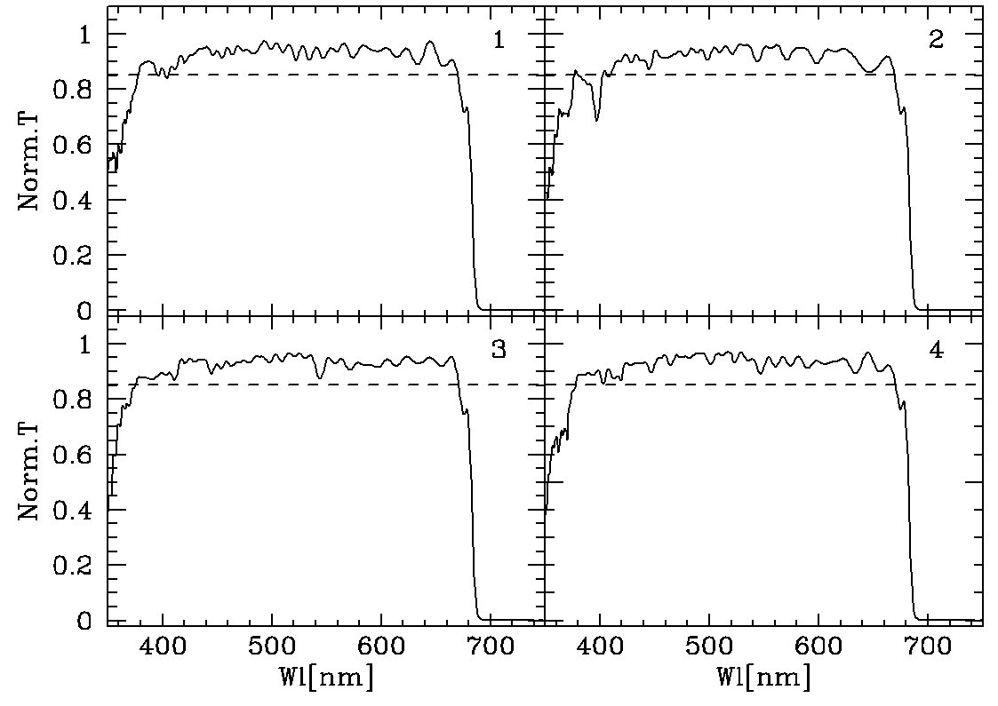
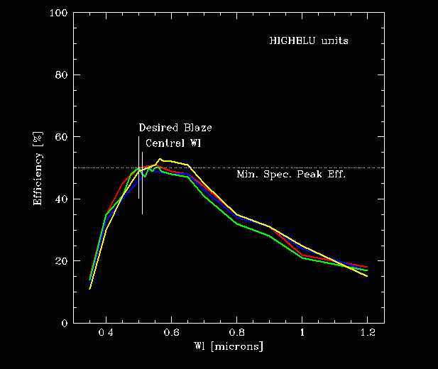
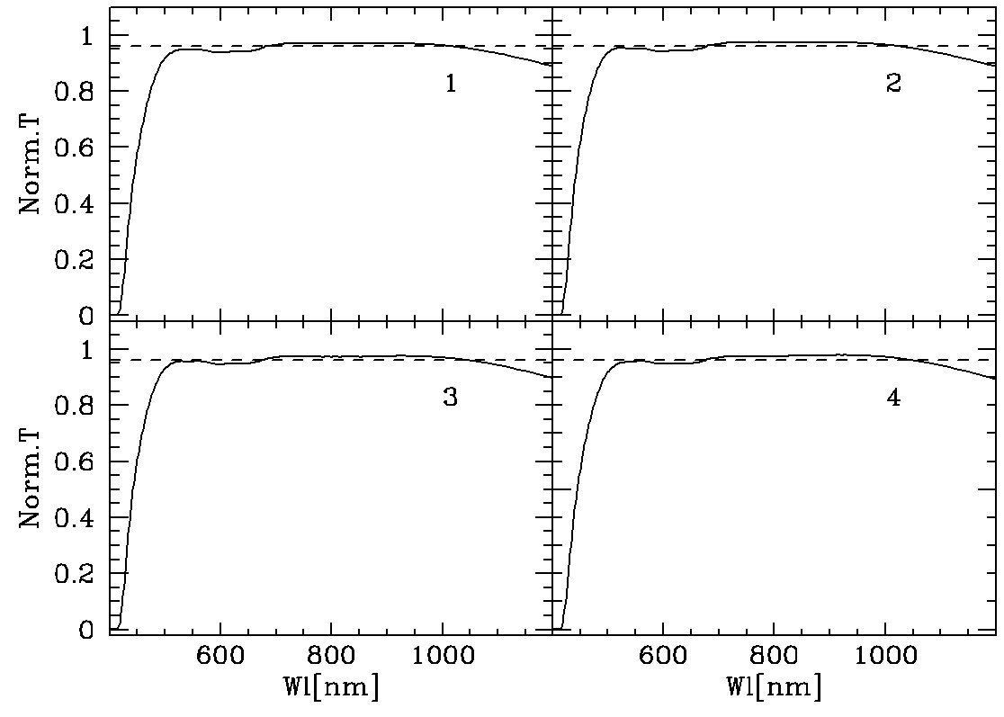
IMPORTANT NOTE (1) A new set of four holographic HR_blue grisms has been installed in VIMOS on March 15 2012. Compared to the previous set, the peak efficiency has increased by about 65% and has moved to approximately 440~nm. The old set is not available anymore.
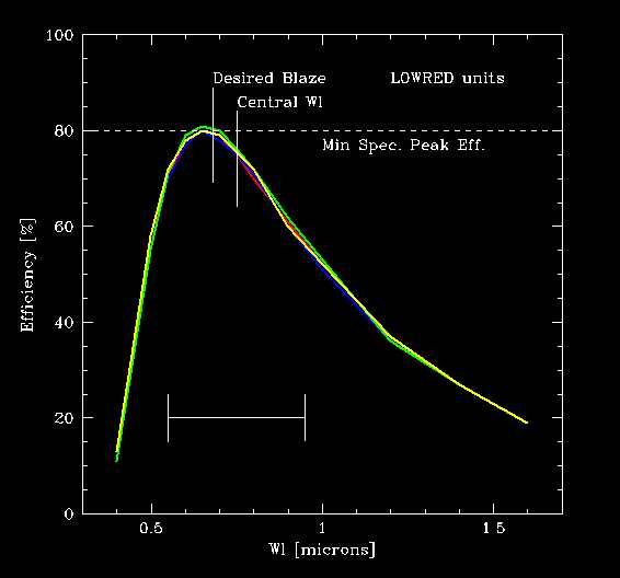
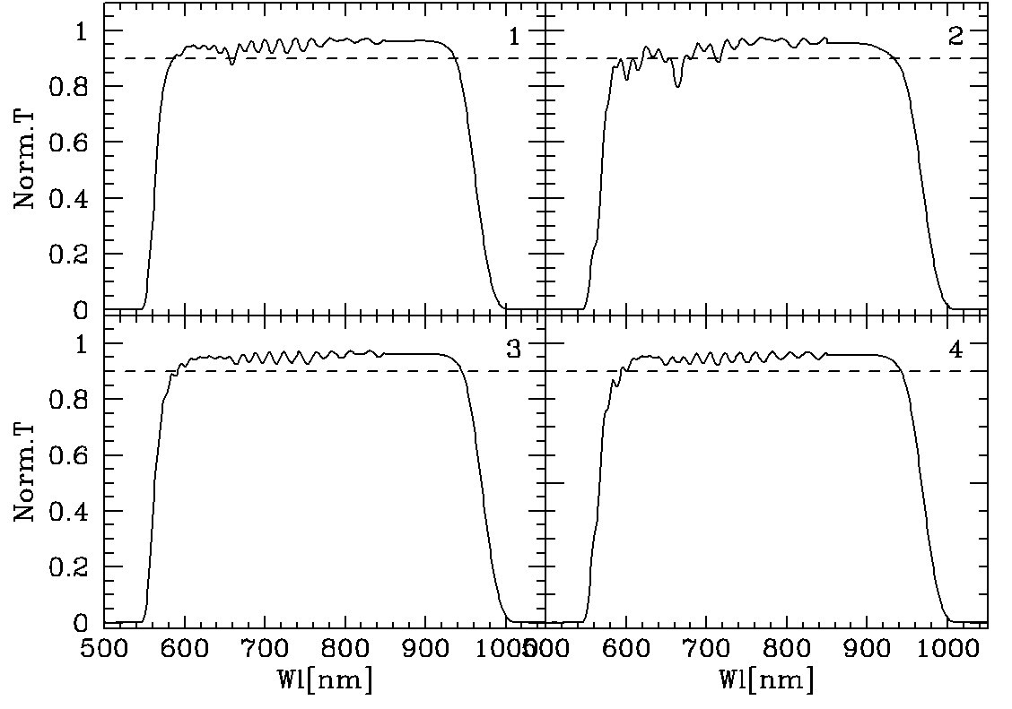
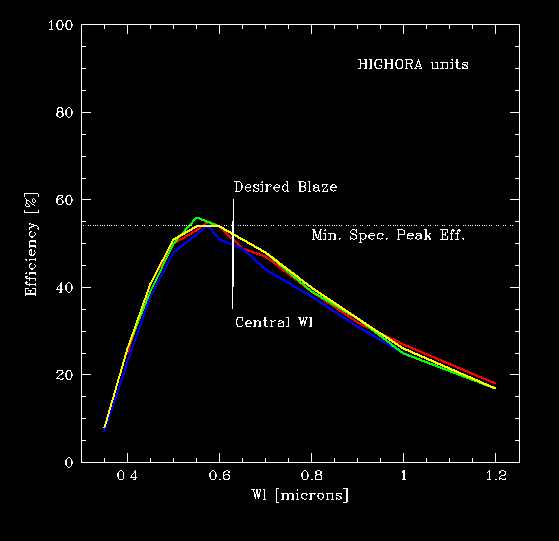
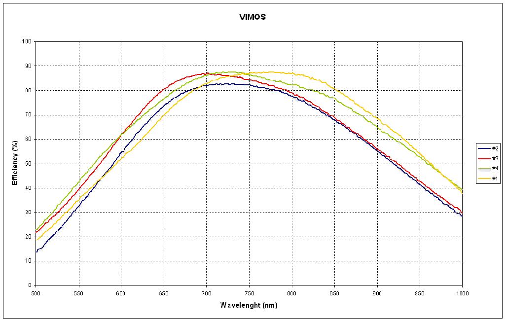
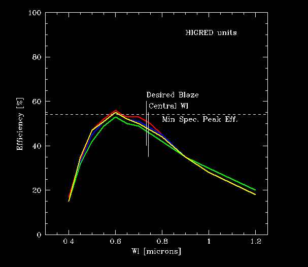
IMPORTANT NOTE (2): A new set of four holographic HR_red grisms has been installed in VIMOS on October 5 2005. Compared to the previousset, the efficiency has increased of about 50%. We remind that before that date, there was no HR_red grism in quadrant 4. The grismHR_orange was instead automatically inserted in quadrant 4 when requesting the grism HR_red. The efficiency curve of the old HR Red grismsis here.
MOS Spectral formats:
In Low Resolution, a spectrum will span 640 pixels along the dispersion direction, for both the blue and red grisms. This allow to stack 4 spectra along the dispersion direction (provided that in the field of view there are enough well spaced targets along the dispersion direction).
At medium resolution, a spectrum will span ~2000 pixels when used with the GG475 sorting order filter.It therefore possible to stack up to 2 spectra along the dispersion direction, provided that the slits are positioned at the edges of the imaging field of view.
At high resolution, a spectra will cover the whole detector length, i.e. 4096 pixels.The spectral coverage is therefore dependent of the position of the slit in the field of view.This is illustrated to the following table.
| Grism | Slit position (1) in the FOV (arcmin) |
Wavelength coverage (nm) |
| LR blue | from -4 to +4 | 370-670 nm |
| LR red | from -4 to +4 | 550-950 nm |
| MR | from -4 to +4 | 500-1000 nm(2) |
| HR red | +4.0 | 705-950 nm |
| HR red | 0 | 630-870 nm |
| HR red | -4.0 | 565-800 nm |
| HR orange | +4.0 | 600-840 nm |
| HR orange | 0 | 520-760 nm |
| HR orange | -4.0 | 455-695 nm |
| HR blue NEW | +4.0 | 370-451 nm |
| HR blue NEW | 0 | 370-535 nm |
| HR blue NEW | -4.0 | 370-624 nm |
(1) Slit positions are 0 (center) and -4.0, +4.0, corresponding to the edges of the imaging field of view along the dispersion direction (8').
(2) the actual spectral coverage depends on the order sorting filter
Another constraints on the slit position is the presence of the zero and second grism diffraction orders.At low spectra resolution, every spectrum at first order will have a dimmed (a few %) second order spectrum, at twice higher spectral resolution, overlapping the adjacent spectrum next to it. This constraints the slit to be of the same height and aligned along the dispersion direction for a clean second order sky substraction.
MOS: Number of slits.
Apart from the geometrical considerations above, the number of slits that can be accommodated in one mask obviously depends on the target density. Simulations made by the consortium on real fields using the Mask Preparation Software show that above a density of ~7E4 per square degree, it is possible to definemasks with up to 650 slits per field (4 quadrants) with slits ~10" long.This number drops to 500 at a density of ~4E4 objects per square degree.
During commissioning up to 1000 spectra were taken on one masks. During ordinary operationsusers routinely create masks with more more than 100 slits (with low resolution grisms).
An example of 2 quadrants with about 100 slits in each mask is shown below
Instrument Flexures
Since August 2010 VIMOS uses an active flexure compensation system. The position of the image in the FoV is fixed during acquisition. During observation a lookup table is used to blindly correct for flexures as the instrument rotates.