
Instrument Description
MATISSE in the VLTI context
MATISSE is a four-telescope beam combiner for the Very Large Telescope Interferometer (VLTI), operating in three mid-infrared atmospheric windows simultaneously; the L, M , and N bands. It is a second generation VLTI instrument that is fully integrated in the VLTI infrastructure. MATISSE can both operate as a standalone instrument and use the fringe tracker of GRAVITY to stabilise the optical path differences of MATISSE (GRA4MAT). In standalone mode, it acts as a coherencer, meaning it will center the entire fringe package after a number of exposures, but not does keep the individual fringes in position. In GRA4MAT mode, MATISSE fringes are locked by the GRAVITY fringe tracker to support the performance of MATISSE
MATISSE Optical Elements
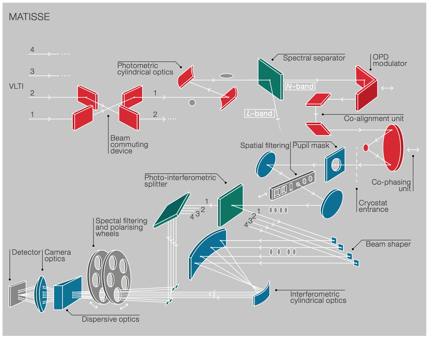
The following is a general description of the optical path, for more detail and numerical information see the instrument manuals.
On the warm optics bench, the beams pass through two commuting devices that can interchange the input beams 1 vs. 2 and 3 vs. 4, respectively. They are always used, and any observation consists of at least one BCD-IN and one BCD-OUT measurement. Comparing the BCD-IN with the BCD-OUT data enables correction of instrument-level chromatic effects on the measured interferometric phases; the correction of similar telescope-level chromatic effects is obtained by comparing science targets to calibrators.
After the LM- and N-bands have been separated inside the warm optics part of the instrument, the beams enter the LM or N-band cryostat. The internal setup of each cryostat is comparable, so this general description is applicable to both cryostats. In an intermediate focus the beams pass through a spatial filter, either a slit or a pinhole, with defined size of the order of the point-spread function. ESO has chosen a standard setup for those, but expert users in visitor mode can make use of the alternative options.
When the photo-interferometric splitter is inserted into the beam, source photometry and fringes are observed simultaneously (SIPHOT mode), otherwise they have to be taken sequentially (HISENS mode). Currently the only offered option is to observe L-band in SIPHOT and N-band in HISENS, which is the so-called HYBRID mode.
Users experienced with N-band interferometry might wish to use the correlated flux measurement provided by MATISSE instead of the full visibility information. Since a correlated flux measurement does not require that source photometry is obtained, the execution time per OB is shorter, and correlated fluxes can be obtained for fainter sources than full visibility measurements. However, in that case the user must have information about at least the calibrator flux from an external source, and preferably the science target as well. Correlated flux measurements are not possible in the LM-band.
The dispersive optics provides a choice of several resolving powers. The detector pixels oversample the optical resolution. For this reason, the pipeline enables binning from spectral pixel to spectral channels, and the performance values are given per spectral channel. This improves the performance limits without sacrificing any recorded astrophysical information. Binning any further would destroy such information. The oversampling (i.e., binning) factors are as follows:
| R | pixel/DIT | pixel/channel | |
|---|---|---|---|
| LR L-band | 34 | 65 | 5 |
| MR L-band | 506 | 118 | 5 |
| HR L-band | 959 | 118 | 5 |
| LR N-band | 30 | 120 | 7 |
| HR N-band | 218 | 819 | 7 |
The "pixels per DIT" are the number of pixels read in spectral direction within the default DIT values.
Filters to reduce the total background are inserted according to the chosen spectral resolution and wavelength range. The polarizing filters are not available for scientific observations.
Interferometric calibrators and calibration strategy
MATISSE if offered with two observing sequences, either CAL-SCI (or SCI-CAL) or CAL-SCI-CAL.
Calibrator stars for N-band and L-band can be found, for instance, with the SearchCal tool provided by the JMMC or through the catalogue published by the MATISSE consortium (see tools). Finding a star that is suitable for both bands at the same time can be tricky. Users should make sure already at phase 1, i.e. for proposal submission, that their chosen calibration strategy is possible and suitable calibrators are available. In case no good L+N calibrators (so called "hybrid" calibrators) are available, the user should consider to use the CAL-SCI-CAL sequence with one calibrator for L-band and one for N-band, this is even more important in case of imaging programs aiming at producing images in both L- and N-band.
The following recommendations should be considered when choosing a calibrator star:
- Mid-IR fluxes are hard to measure. It is recommended to compute median fluxes in L and N bands using for example the VizieR Photometry viewer provided by CDS-SIMBAD intead of relying on a single source.
- Good calibrators should follow the Rayleigh-Jeans approximation, i.e., avoid IR excess. L/N-band flux ratio (at 3.3 and 8.5 microns) should best be within a range of 7 to 9.
- A SIMBAD search on the calibrator should show "star" as object type.
MATISSE in P117 and P118
MATISSE is offered in as stand-alone instrument and with GRAVITY fringe tracker (GRA4MAT mode), on all the standard ATs configurations and on the UTs. With the UTs it is offered in NGS-VIS and in LGS-VIS mode. Note that the LGS/NGS IR modes of GPAO on the UTs is currently not offered for MATISSE. Please find below more details of the modes offered.
Execution Times
| Setup | single OB | CAL-SCI | CAL-SCI-CAL |
|---|---|---|---|
| Low L and M-band | 20 min | 40 min | 60 min |
| Medium L and M-band | 20 min | 40min | 60 min |
| High and high+* L-band | 25 min | 50 min | 75 min |
| N-band photometry** | +10 minutes | +20 minutes | +30 minutes |
* The High+ mode is only available with GRA4MAT.
** During the N-band photometry exposures, LM-band data (fringes + photometry) are simultaneously recorded with chopping. We strongly reccomend to includes such observations. For details of when such exposures can be skipped, please see the User Manual.
MATISSE stand-alone
- Hybrid is the only observing mode offered. The hybrid mode consists of the following two steps: 1. acquisition of fringes in SiPhot mode LM + HiSens mode N; 2. SiPhot with chopping in LM + Photometry in N. Users interested only in closure and differential phases can skip step 2. All the other users are asked to include step 2 (i.e. the additional time needed to record the N-band photometry, see table "Execution Times" and Overheads)
- L-band observations are offered with low (R=34), medium (R=506), and high (R=959).
- M-band observations are offered with low (R = 34) and medium (R = 506) resolution. M-band measurements need the photometry step.
- N-band observations are offered with low resolution (R=30) and high resolution (R=218).
- The DIT values are fixed. The chosen DIT for LM-bands enables to observe a spectral window of 0.08 micrometer in high resolution, and 0.16 micrometer in medium resolution, which the user can center following the table below. In visitor mode the user can center the spectral window freely. The central wavelengths available in low spectral resolution in service mode are 3.5 and 4.1 micrometers.
| Setup | Central wavelength | Spectral feature |
|---|---|---|
| Medium and high L-band | 3.03 | Pfund 10-5 |
| 3.05 | Water ice | |
| 3.17 | C2H2, HCN, CN | |
| 3.3 | PAH | |
| 3.4 | CH | |
| 3.52 | Nano-diamonds | |
| 3.77 | C2H2 | |
| 3.88 | C2H2 | |
| 3.95 | C2H2 | |
| 4.0 | SiO | |
| 4.05 | Bracket Alpha | |
| Medium M-band | 4.65 | Pfund 7-5 |
| 4.78 | CO |
Sensitivity and Errors vs. Observing Conditions
General
The limiting magnitudes for MATISSE standalone given below are listed for two atmospheric turbulence categories. However, bad observing conditions do not only diminish the flux. If a science case is critically dependent to achieve the best possible error bars, it is strongly recommended to request good observing conditions regardless of the target brightness. Observations at seeing values worse than 1.2" are not recommended. All flux limits are given in Jansky and they correspond to correlated fluxes (Flux at a given band times Visibility). Details about the commissioning of MATISSE and the derivation of the instrument performances are described in Petrov et al. 2020. Small differences between the paper and the here published data are given by the fact that difference turbulence categories are used. The numbers provided below are the reference to be used for the call for proposal.
The extended AT-array configuration relies on additional optics to increase the delay line stroke and thus sky coverage. For MATISSE, these additional reflections mean that all limiting fluxes below have to be considered as to be 30% worse for observations on the extended configuration.
Absolute measurements
For closure and differential phase as well as visibility measurements the following limits will allow to achieve a precision per spectral channel at least as good as:
- For visibilities a precision of 0.1
- For coherent flux (N-band only) of a SNR of 10
- 4 deg for the differential phase
- 5 deg for the closure phase
The limit in low resolution is mostly caused by uncertainty of the photometry and independent of the binning. This limits the precision of the visibilities, not of the detection of fringes themselves. For specific science cases, usable information such as variation of some measurements with wavelength or baseline can be obtained at substantially lower magnitudes. Please contact the instrument scientist for such limits.
| Setup | AT | UT | ||
|---|---|---|---|---|
T≤ 30% Seeing ≤ 0.8" τ0 > 4.1 ms |
T≤ 70% Seeing ≤ 1.15" τ0 > 2.2 ms |
T≤ 30% Seeing ≤ 0.8" τ0 > 4.1 ms |
T≤ 70% Seeing ≤ 1.15" τ0 > 2.2 ms |
|
| Low L-band | 1 Jy | 1.5 Jy | 0.06 Jy | 0.08 Jy |
| Low M-band | 2 Jy | 5 Jy | 0.11 Jy | 0.11 Jy |
| Medium L-band | 8.5 Jy | 10.5 Jy | 0.6 Jy | 0.7 Jy |
| Medium M-band | 13 Jy | 16 Jy | 1.3 Jy | 1.6 Jy |
| Low N-band* | 17 Jy | 17 Jy | 1.0 Jy | 1.3 Jy |
* Values are for the N1 sub-band, centered on 8.5microns. If a target is exremely red or quality of masurement is critical at longer wavelengths, see text. Also, since the quality of photometriy a limiting factor for the N-band visbility, these values are for the total flux, not the correlated fluxes as for the other entries.
It was noticed back in Aug 2020 that stand-alone N-band measurements observations of faint sources (N bands fluxes fainter than about 6-8 Jy at 8 and 11 micron respectively) are affected by a bias introduced by the piston correction. Such bias is removed if the GRA4MAT mode is used.
The N-band can be subdivided into N1 (8.5+-0.4micron), N2 (10.5+-0.5 micron), and N3 (11.5+-0.5 micron). If the object is extremely red, or the above defined precision is required in N2 or N3 bands, the following limits apply: For ATs: N2 brighter than 32 Jy, and N3 brighter than 45 Jy. For UTs: N2 brighter than 1.5 Jy, and N3 brighter than 2 Jy.
Correlated flux measurements
For weak targets, photometric measurements become too noisy to normalise in real time the raw correlated flux measurements to form the visibilities. Instead, direct measurement of the correlated fluxes (=absolute fringe amplitudes) is possible. Since correlated flux measurements are, in essence, spectrophotometric measurements on faint targets, they are only offered for good observing conditions and low spectral resolutions. Absolute calibration of correlated fluxes requires special calibrators, as not only their sizes need to be known, but also their SED. If you are interested in using the correlated flux mode and have doubts about your calibrators, you can contact the VLTI Expertise Centre at Leiden Observatory for help with selecting appropriate calibrators and data reduction.
| Setup | AT | UT |
|---|---|---|
T≤ 30% Seeing ≤ 0.8" τ0 > 4.1 ms |
||
| Low L-band | 0.3 Jy | 0.04 Jy |
| Low M-band | 1.1 Jy | 0.04 Jy |
| Low N-band | 6 Jy | 0.5 Jy |
Relative measurements
For medium and high resolutions, additional limits are given for measurements where only the differential phase is considered, since absolute measurements are better obtained with low resolution setting. Since relative measurements are not as susceptible to sky conditions as absolute measurements, they need not be made under good conditions. We give the limiting magnitudes to achieve a precision of 4 degree per spectral channel in differential phase, and an SNR on the coherent flux in N-band (see above for definition of spectral channel):
| Setup | AT | UT |
|---|---|---|
T≤ 70% Seeing ≤ 1.15" τ0 > 2.2 ms |
||
| Medium L-band | 5.6 Jy | 0.35 Jy |
| Medium M-band | 8 Jy | 0.8 Jy |
| High L-band | 10 Jy | 1.2 Jy |
| High N-band | 25 Jy | 1.1 Jy |
GRA4MAT mode
The use of GRA4MAT is recommended as soon as fringe tracking is possible on a MATISSE science target
Limiting fluxes derived from the last commissioning run and offered on the ATs are the following:
| spectral mode | lowest L flux (Jy) | lowest M flux (Jy) | lowest N flux* (Jy) | |||
|---|---|---|---|---|---|---|
| corr. Flux & diff phase | closure phase | corr. Flux & diff phase |
closure phase | corr.Flux & diff phase | closure phase | |
| LOW (R~35) | 0.2 | 0.25 | 0.7 |
1 |
3 |
5 |
| MED (R~500) | 1 | 1.5 | 11 | 16 | not offered | not offered |
| HIGH (R~1000) | 2 | 3 | not offered | not offered | 26 (R ~ 220) | 30 (R~220) |
| HIGH+ (R~3300) | 20 | 25 | 17 | 25 | not offered | not offered |
The Limiting magnitude for GRAVITY's Fringe Tracker depends on the atmospheric conditions as follows:
| Occurence probability | 10% | 30% | 70% |
|---|---|---|---|
| Seeing | <0.6" | <0.8" | <1.15" |
| Coherence Time | >5.2 ms | >4.1 ms | >2.2 ms |
| K mag | <8.5 | <8.0 | <7.0 |
Limiting fluxes derived from the last commissioning runs and offered in P117 and P118 on the UTs with GPAO (NGS and LGS):
| spectral mode | lowest L flux (Jy) | lowest M flux (Jy) | lowest N flux* (Jy) | |||
|---|---|---|---|---|---|---|
| corr. Flux & diff phase | closure phase | corr. Flux & diff phase |
closure phase | corr.Flux & diff phase | closure phase | |
| LOW (R~35) | 0.01 | 0.03 | 0.03 | 0.04 | 0.1 | 0.4 |
| MED (R~500) | 0.04 | 0.06 | 0.35 | 0.45 | not offered | not offered |
| HIGH (R~1000) | 0.12 | 0.16 | not offered | not offered | 0.5 (R ~ 220) | 0.7 (R~220) |
| HIGH+ (R~3300) | 1 | 8 | 6 | 8 | not offered | not offered |
The limiting magnitude for GRAVITY's Fringe Tracker (K band) depends on the atmospheric conditions as follows:
| Occurence probability | 10% | 30% | 70% |
|---|---|---|---|
| Seeing | <0.6" | <0.8" | <1.15" |
| Coherence Time | >5.2 ms | >4.1 ms | >2.2 ms |
| K mag | 13.0 | 12.5 | 11.5 |
- The user should select the turbulence category based on the K band magnitude of the source in p1.
- For GRA4MAT mode in p1 the user should select the precipitable water vapor to be 5mm or less in the line-of-sight, since fringe-jumps, causing loss of signal and hence reducing the SNR, occur much more frequently at higher water vapour content of the atmosphere.
- Spectral coverage goes as follow: LOW and MED cover the full L and M-bands. HIGH is limited to L-band, and HIGH+ covers 3.97 - 4.11 microns in L ((it covers the Br-alpha hydrogen line) or 4.56 - 5.14 micron in M. The user should refer to the Template manual to select the DITs and central wavelenghths covering the desired wavelength regimes.
- All targets with correlated flux N-band < 1 Jy (UTs), and N-band fluxes <6-8 Jy (at 8 and 11 micron respectively, ATs) should be observed with GRA4MAT to avoid a bias in the measurement.
- The execution time for a calibrated OB in GRA4MAT mode follows the same rules as MATISSE stand-alone, and it is given in the table on top of this page. The user will need to select GRA4MAT template already at phase1 and select the photometry on or off depending on the requirements of the program and the telescopes used. Whether a photometry sequence is possible, see below for chopping.
- When in doubt on the K-band flux injected into the GRAVITY fibre (as is often the case for extended targets with only integrally measured values), it is recommened to give a conservatively lower K-band magnitude in the OB, to ensure the fringe tracker runs in an appropriate mode with a longer DIT.
Narrow field off-axis observations
From P112 onwards GRA4MAT is offered with the capability to track fringes with GRAVITY, while MATISSE points to a nearby offset position to record fringes. This is useful to observe, e.g., planets or brown dwarf companions to stars that can be tracked by GRAVITY, when the relative position is well known. In principle, the same performance limits as for on-axis observations apply (see tables above). However, for small offsets the contrast between the central star and the off-axis target might prove problematic and users should take the different size of the point-spread functions of UTs vs. ATs into account when proposing observations. The maximum distance from the central target is 1 arcsecond for UTs and 3 arcseconds for ATs. Offsets can be defined in the normal GRA4MAT observing template. A cumulative sequence of offsets can be given in a single template. Data from the commissioning of this mode is available for β Pictoris and a calibrator. While normal MATISSE observations require to strictly have one science template only, a waiver can be obtained to add more than one for the narrow field off-axis mode in order to realise different exposure times for different offset positions.
The narrow field off-axis mode is offered in service mode. The chopping sequence is not supported. For data reduction of the narrow field off-axis the users should contact the VLTI Expertise Centers.