
Instrument Description
What MUSE does
MUSE is an Integral Field Spectrograph. It splits the field of view into 24 image segments or channels which are further sliced into 48 slices or mini slits, giving a total of 1152 mini slits. Each set of 48 mini slits is injected into one of the spectrographs to produce a set of medium resolution spectra.
In Wide-Field Mode (WFM), MUSE splits a field of 1 arcmin2 into 24 channels which are further sliced into 48 15"x0.2" slitlets.
Starting in P101, in addition to the natural seeing or NOAO mode, MUSE has been offered in Wide Field Mode with Ground Layer Adaptive Optics (GLAO) using the GALACSI module. Starting in P103 GALACSI started to deliver a laser tomography adaptive optics (LTAO) corrected field covering a 7.5" x 7.5" field of view (Narrow-Field Mode, NFM), providing near diffraction limited images with a sampling of 0.025" per spatial pixel. GALACSI is part of the Adaptive Optics Facility, AOF, an AO system developed to increase the performance of MUSE, using a 4 laser guide star (LGS) system and a deformable secondary mirror to provide a wave-front corrected for the turbulent atmospheric ground layer in WFM and tomographic correction in NFM.

Starting P101 MUSE is offered with GALACSI in GLAO mode.

Narrow Field Mode offered starting in P103.
Splitting and slicing of the field
In WFM, the 1'x1' field of view is split into 24 slices and each sent to a separate integral-field unit (IFU, top left). Each IFU further arranges each slice into 48 slitlets (top right). The spectra produced are arranged on each detector according to the schematics below (bottom).


Spectrograph
The main function of the spectrograph is to produce the spectra of the mini slits and image them onto a detector. It is composed of a collimator, a Volume Phase Holographic Grating (VPHG) and a camera. The grating disperses the slitlets in the perpendicular direction and achieves a spectral resolution of 1770 at 465nm to 3590 at 930nm.

MUSE Performance
The absolute throughput of the overall system, MUSE+Yepun, has been measured by observing spectrophotometric standard stars during commissioning. The throughput in both modes peak to a high value of 35% at around 700 nm, and is overall >15%. At shorter wavelengths, the throughput in the nominal mode, WFM-NOAO-N, drops to zero around 480nm, while the extended mode, WFM-NOAO-E, gives a non-zero thorughput down to 465 nm. For actual estimates of integration times, S/N, etc, we refer the user to the MUSE ETC.

Instrument description
The different components of the instruments are illustrated below.

Fore Optics
The Fore Optics (FO) reshape the VLT focus image to adapt it to the next subsystem which splits the image in 24 channels. The main moving functions implemented in the FO are to derotate the Nasmyth Field of view, to select the instrumental mode (WFM or NFM) with the Mode Switching Unit, to adjust the dispersion in NFM with the Atmospheric Dispersion Corrector (ADC), and to select one of the filter positions from the filter wheel. An Anamorphoser magnifies the beam in the vertical direction. A NACE CCD is used to implement the Slow Guiding System which aims is to correct for small residual displacement between the Telescope and the MUSE focal plane. The Exposure shutter is also located in the FO.

Derotator
The derotator compensates for the field rotation happening at the VLT Nasmyth focus. It is a classical derotator based on two prisms: when rotated by an angle α, the image plane rotates by the angle 2α.
Mode-switching unit and Atmospheric Dispersion Corrector
The Mode-switching unit prepares the field of view when the instrument is used in NFM. It adds a magnification of x8 in each direction and includes the ADC. The ADC is used, in NFM mode only, to correct for atmospheric dispersion. It consists in two Amici prisms working in counter-rotation.
IRLOS
A dichroic reflects the infrared light towards IRLOS, a 2x2 Shack-Hartmann wavefront sensor observing the scientific object in the infrared for AO correction. It also senses image drifts occurring in NFM and corrects them by means of the AO loops.
Filter Wheel
A filter wheel is included in the fore-optics to adjust the spectral coverage according to the desired instrument mode:
- The nominal wavelength range of MUSE corresponds to 480--930 nm, which allows for suppression of second-order contamination in the red.
- An “extended” wavelength range is available in WFM, allowing observations down to 465 nm. However, strong second-order contamination appears in that case at λ>900 nm (see User Manual for details).
- In addition, the wavelength region surrounding the Na emission (584--594 nm) is suppressed when the instrument is used with AO correction.
Anamorphoser
Two cylindrical mirrors provide a magnification of 2 to the beam in the vertical direction within the fore-optics.
Slow Guiding System (SGS)
When in WFM mode, an elliptical pick-up mirror separates the central field-of-view from the four ‘banana-shaped’ metrology fields at the edges of the circular beam, which are reflected towards the Slow Guiding System, after removing the magnification. Incoming light is recorded by the SGS using a NACE 1k x 1k Technical CCD (having a 0.09” pixel scale in WFM). The system automatically detects astrophysical sources in the metrology fields and corrects for small motions by sending commands to the telescope in a closed loop.

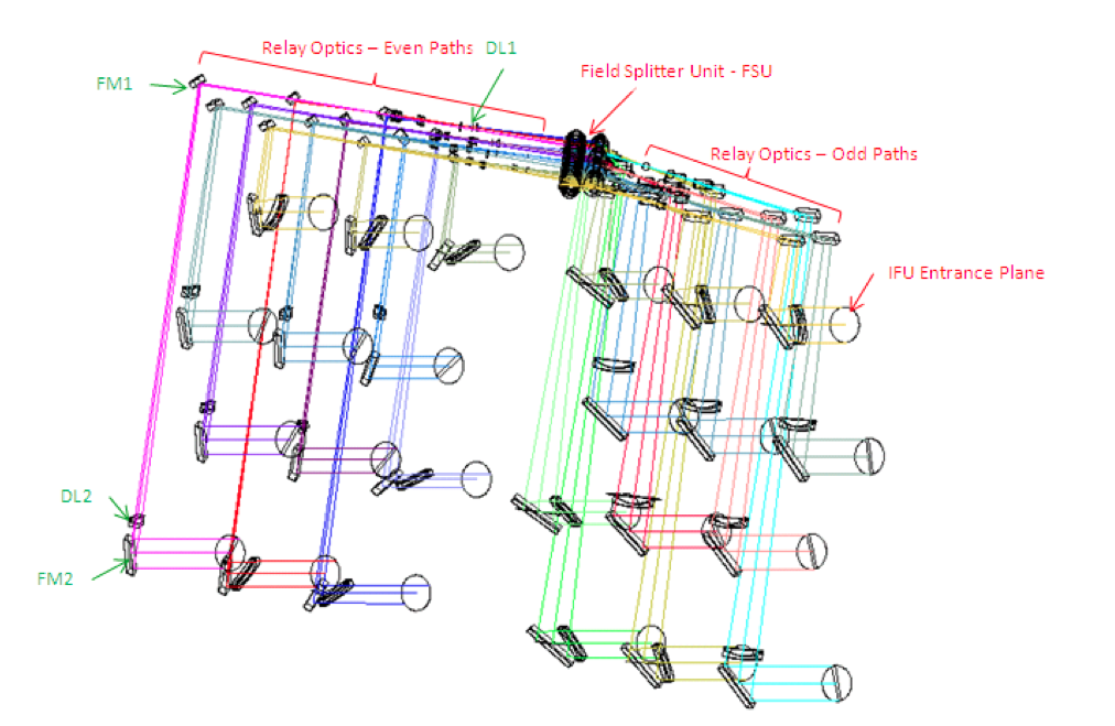
Split and relay Optics (SRO)
The SRO system splits the MUSE field-of-view into 24 channels and redirects the light of each channel towards the entrance of an IFU. It is composed of a field-splitter and a field separator, which separate the beams, and 24 relay optics, which correct for the variations in optical path from one channel to another.


Integral Field Units (IFUs)

Slicer
The slicer cuts and rearranges the 2D sub field of view in a 1D pseudo slit of 0.2" width (for WFM). The main function of the image slicer is to slice the fraction of the field-of-view coming from the SRO into 48 slitlets that are rearranged in a long slit at the entrance of the spectrograph. The slicer is composed of an image dissector array, which separates the beam in 48 slices (as represented in the top-right panel), a focusing mirror array, which rearranges and aligns the slices, and the pupils/slits mask, which reduces scatter light and ghost images before entering the spectrograph.

Spectrograph
The main function of the spectrograph is to produce the spectra of the slitlets and image them onto a detector. It is composed of a collimator, a Volume Phase Holographic Grating and a camera. The grating disperses the slitlets in the perpendicular direction and achieves a spectral resolution of 1750 at 465nm to 3750 at 930nm


Detectors
The light exiting each of the 24 spectrographs is sent onto a 4k x 4k, 15 μm pixel CCD, operating at 163 K. The full characteristics of these detectors are given in the table.
New Generation Controllers (NGC)
The twenty four scientific detectors of MUSE are controlled using four New Generation Controllers (NGC). A summary of available read-out modes for the 24 CCDs is given below. The SCI1.0 is always used without binning during observation. A 1x4 binning is used for fast image reconstruction only. The FAST read-out mode is only used in engineering mode.
Parameter |
Value |
CCD Type |
EEV Deep depletion, AR graded coated |
|
Active pixel format |
4096 x 4112 pixels (X x Y) |
|
Pixel size (microns) |
15 x 15 microns |
|
Pixel scale (Nasmyth focus) |
0.20 arcsec pixel-1 (WFM) |
|
Pre-scan pixels in X direction |
32 |
|
Overscan pixels |
32 |
|
Detector gain (ADU/e-) |
1.1 |
|
Saturation |
65000 e- |
|
Readout noise (e-) |
2.6 |
|
Number of readout ports |
4 |
| Readout speed | 100 kpix/s |
| Readout time to RTD | 40 s |
|
Dark current at 160k |
3 e- pix-1 hr-1 |
Calibration unit
The calibration unit (CU) is a mechanical structure with calibration lamps, an integrating sphere, and a set of masks used to produce calibration fields for MUSE. A calibration pick-up mirror allows to select between the Telescope and the CU as the MUSE entrance light beam. The CU allows for a choice of 6 calibration lamps as input light sources:
- Two flat-field halogen lamps providing uniform continuum flux over the MUSE wavelength range
- 4 arc lamps used for wavelength calibration:
- One Ne pencil-ray lamp
- One Xe pencil-ray lamp
- One HgCd pencil-ray lamp
- One Ne High Power lamp
- Two pico-ampere meters placed at the CU focal plane are used to monitor the absolute flux sent by the lamps into MUSE. Details on the line wavelengths and relative fluxes produced by each lamp are provided.
The old logbook of changes affecting data reduction ca be found here. It is superseded by the Event Log table found in the News section.