
Polarization Observations with FORS
FORS2 can measure linear polarization and circular polarization in imaging and spectroscopic modes. It is possible to determine position angle and degree of the linear polarization or the circular polarization of an object by using a remotely controlled rotatable lambda/2- or lambda/4-plate in front of the Wollaston prism.
Description of the FORS Polarization Modes
The retarderplates are of the "superachromatic'' type (after Serkowski). The waveplates are mosaics of 3*3 plates of 45.5*45.5mm each are used (inter-plate gap 3mm) with a resulting free mosaic diameter of 138mm. The position angles can be set with an accuracy of 0.1 degree.
One is required to correct for chromatic zero angles in case of linear polarimetry. This is explained in the User Manual in more detail. The figure below shows the amount of chromatism of the wave plate. The data for the plot are also available in tabulated and ascii format which have been measured with a Glan Thomsen Prism (which was mounted at the M2 spider and aligned):
Optical Components
 |
 |
| Wollaston Prism | Retarder Plate |
|---|
Polarimetric Standard Stars
The following list of polarimetric standard stars has been provided by the FORS consortium based on Commissioning data taken with FORS1. There are prepared OBs available on Paranal, as well as selected unpolarized targets. Please note that there are additional errors not included in the error budget, for instance with broad band filters the zero angles of the retarder plates will depend slightly on the colour of the target. This is the most likely reason why Vela1 95 or Hiltner 652 have these odd values for the polarization position angle in U and B. The targets are selected from Whittet et al. (1978) or from the catalog of Mathewson and Ford (1970). NGC 2024 NIR1 was suggested by I. Appenzeller.
| star | filter | mag. | p in % | PA in degree |
| NGC 2024 NIR1 | B | 13.75 | 8.27 +- 0.03 | 137.6 +- 0.1 |
| V | 12.10 | |||
| M78 HD 38563A | B | 3.42 +- 0.04 | 96.1 +- 0.4 | |
| V | 10.42 | |||
| Vela1 95 | U | 6.59 +- 0.15 | 169.8 +- 0.7 | |
| B | 7.55 +- 0.05 | 173.8 +- 0.2 | ||
| V | 12.1 | 8.24 +- 0.03 | 172.1 +- 0.1 | |
| R | 7.89 +- 0.04 | 172.1 +- 0.2 | ||
| I | 7.17 +- 0.04 | 172.2 +- 0.2 | ||
| Hiltner 652 | U | 5.03 +- 0.04 | 179.7 +- 0.2 | |
| B | 5.72 +- 0.02 | 179.8 +- 0.1 | ||
| g | 6.18 +- 0.04 | 179.6 +- 0.2 | ||
| HDE 316232 | B | 10.97 | 4.57 +- 0.02 | 4.3 +- 0.2 |
| V | 10.29 | |||
| BD -14 4922 | B | 10.58 | 5.62 +- 0.04 | 50.5 +- 0.1 |
| V | 9.73 | |||
| BD -12 5133 | B | 11.5 | 4.32 +- 0.05 | 148.4 +- 0.3 |
| V | 10.8 |
A real example for a standard star measurement - calibration plan data taken 2002-04-04
Unpolarized nearby star WD1620-391 - R_BESS
| angle | f_o | f_e |
|---|---|---|
| 0 | 28229 | 28454 |
| 22.5 | 28282 | 28403 |
| 45 | 28396 | 28519 |
| 67.5 | 28290 | 28522 |
                 f_o - f_e                    f_o - f_e

    Q/I =  0.5 * --------- ( 0.0 deg) - 0.5 * --------- (45.0 deg) = -0.001

                 f_o + f_e                    f_o + f_e


                 f_o - f_e                    f_o - f_e

    U/I =  0.5 * --------- (22.5 deg) - 0.5 * --------- (67.5 deg) =  0.001

                 f_o + f_e                    f_o + f_e
The flux integrated in a wide aperture is given in adu (with 1.46 e-/adu since the flats in the lower left quadrant have been normalized - 4-port mode). f_o and f_e are the flux in the ordinary (top) and extraordinary (bottom) beam of the Wollaston. The result is pretty consistent with readout noise of about delta Q / Q = 0.5 / sqrt(28400 * 2 * 1.46).
Polarized highly reddened star Vela1 95 - R_BESS
| angle | f_o | f_e |
|---|---|---|
| 0 | 29324 | 25387 |
| 22.5 | 26313 | 28002 |
| 45 | 25139 | 29794 |
| 67.5 | 28056 | 26630 |
                 f_o - f_e                    f_o - f_e

    Q/I =  0.5 * --------- ( 0.0 deg) - 0.5 * --------- (45.0 deg) =  0.078

                 f_o + f_e                    f_o + f_e


                 f_o - f_e                    f_o - f_e

    U/I =  0.5 * --------- (22.5 deg) - 0.5 * --------- (67.5 deg) = -0.029

                 f_o + f_e                    f_o + f_e


      p = sqrt(Q**2 + U**2) =   0.083


  theta = 0.5 * atan(U/Q)   = 169.8


theta_0 = theta + 1.2       = 171.0   (see FORS user manual chapter 4)
According to the FORS User Manual the retarder plate zero angle -1.2 degree has to be subtracted for the measurement with the R_BESS filter and the final result is 171.0 degree accordingly. One should note that only generic bias frames and generic imaging twilight flats (no Wollaston, no half wave plate) are provided as part of the calibration plan and thus used for data reduction. Flatfielding with flats taken separately at 0, 22.5, ... degree retarder plate angle will diminish the instrument performance dramatically, since the flat field structures are not anymore nulled (1st order approx.) in the equations for Q and U.
Instrumental polarization:
Strong linear instrumental polarization in the corners of the field of view is seen with FORS2. This spurious polarization field shows a high degree of axial symmetry, which smoothly increases from less than 3x10^{-4} on the optical axis to 7x10{-3} at a distance of 3 arcmin from it (V band). (Also see Gonzalez-Gaitan et al. 2020.)
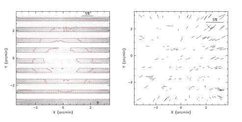
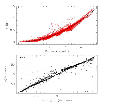
In case of the V band the spurious polarization can be modeled with a radial function:
PA(x,y) = arctan( (y-yc) / (x-xc))
depending on the radial distance from the center of the field of view (xc,yc) and the position angle PA(x,y).
In case of the other filters and spectro-polarimetric measurement there is no data available yet. The corrective functions can be estimated with an observation of a globular cluster (like 47 Tuc) with the respective filters. For those cases in which the correction of the spurious polarization is critical for your science please go to the ESO support desk at: https://support.eso.org.
Please note that there should be no problem for spectro-polarimetric observation of single targets in the center of the field of view or single targets in imaging polarimetry in the center of the field of view. In case of the circular polarization the spurious polarization was found one order of magnitude smaller (see Bagnulo et al. 2002).
Further information regarding the calibration of FORS polarimetry data can be found in our list of technical papers.